-
Product Listing
Directional Fault Indicators
Product Features
-
Fault Detection : Directional Short Circuit | Directional Static Earth | Directional Transient Earth | Earth Fault Via Pulse Locating | Earth Short-Circuit
-
Fault Reset Option : Auto | Manual | Remote (Modbus)
-
Measurement Parameters : Current | Voltage
-
Control Type : Push Button
-
Step Voltage Monitoring : Yes

Enhance your grid reliability and minimize downtime by monitoring faults and earth faults on single phase conductors up to 52 kV
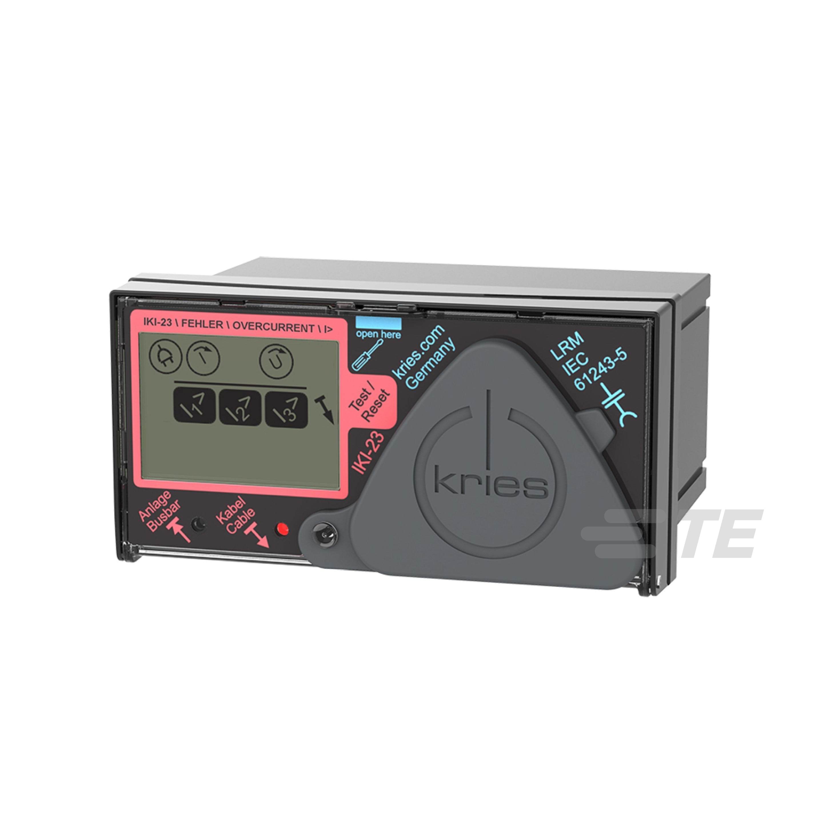
The TE Connectivity (TE) Kries IKI-23 directional fault current indicator is designed for switchgears, underground distribution and transmission lines from 3 to 52 kV. Efficient fault detection and an immediate response are crucial for maintaining the reliability of your power grid. Our Kries IKI-23 fault indicator is designed to monitor fault conditions such as short circuits, temporary disruptions, and ground faults on single-phase and/or three-phase underground power grids, helping grid operators to restore power after unplanned outages quickly.
When combined with our CAPDIS voltage detection system, the IKI-23 can provide precise directional fault indication. This advanced feature allows operators to quickly and accurately identify the direction of the fault, significantly reducing the time required to locate and isolate faults.
Engineered for durability, the IKI-23 is compliant with IEC and IEEE standards, and its design helps ensure consistent performance in harsh conditions from -25 °C to +55 °C (-13 °F to +131 °F), enhancing grid reliability and reducing costs.
Designed for seamless integration, our IKI-23 fits easily into existing systems with minimal disruption. The user-friendly installation process allows for quick setup and configuration, enabling immediate benefits in both grid reliability and reduced downtime.

Key Features
Directional and nondirectional fault detection with CAPDIS
- Integrated diagnostic function
- Event memory
- Step voltage warning
Applications

Question: What is a directional fault indicator?
Answer: A directional fault indicator is a device that is used in power distribution networks to detect and indicate the direction of a fault. This helps operators to quickly locate and isolate faults, which minimizes downtime and improves the reliability of the power grid.
Question: How does the TE Kries IKI-23 work?
Answer: This device uses sensors to detect abnormal current levels and provides a signal when a fault is detected, helping to quickly identify its location.
Question: What are the benefits of using IKI-23?
Answer: Rapid fault localisation quickly identifies the direction of the fault, which reduces the time needed to locate and repair issues - leading to the following benefits:
- Improved reliability: Enhances the power grid's reliability by minimising downtime and preventing extended outages.
- Cost savings: Reduces the operational costs associated with prolonged fault-finding missions and repairs.
- Increased safety: Provides accurate fault information, enabling safer, more efficient fault management.
Question: What is the difference between a standard fault indicator and a directional fault indicator, such as IKI-23?
Answer: A standard fault indicator detects the presence of a fault but does not indicate its direction. A directional fault indicator not only detects the fault but also indicates the direction in which it occurred, providing more precise information for troubleshooting.
Question: What type of maintenance does the TE Kries IKI-23 require?
Answer: IKI-23 is designed for low maintenance. Regular inspections and battery checks are recommended to support optimal performance, but the device itself is built for durability and long-term reliability.
Please review product documents or contact us for the latest agency approval information.
Product Type Features
-
Monitoring Options PD Trend Monitoring
-
Control Type Push Button
Configuration Features
-
Configuration Method DIP Switches Behind Front Panel
-
Relay Output Configuration Configurable
-
Number of Digital Inputs 1
-
Number of Feeders 1
-
Number of Voltage Inputs 1
-
Number of Relay Outputs 4
Electrical Characteristics
-
Short Term Current Measurement Range (A) 5 – 2000
-
Nominal Voltage Range (kV) 1 – 52
-
Power Supply Capacitor | Sensors
-
Continuous Current Measurement (Max) (A) 800
-
Step Voltage Monitoring Yes
Dimensions
-
Case Width 98 mm [ 3.86 in ]
-
Case Depth 97 mm [ 3.82 in ]
-
Case Height 50 mm [ 1.97 in ]
Usage Conditions
-
Operating Temperature Range -25 – 55 °C [ -13 – 131 °F ]
-
Storage Temperature Range -25 – 70 °C [ -22 – 158 °F ]
Operation/Application
-
Network Application Type Underground
-
Communication Interface Mini-USB | Modbus RTU (Slave)
-
Measurement Parameters Current | Voltage
Industry Standards
-
IP Rating IP54
Other
-
Battery Type Lithium
-
Fault Recording Type Event Recording
-
Network Neutral Earthing Inductive Terminated Neutral | Isolated Neutral | Low Ohmic Terminated Neutral | Short Term Low Ohmic Terminated Neutral
-
Fault Detection Directional Short Circuit | Directional Static Earth | Directional Transient Earth | Earth Fault Via Pulse Locating | Earth Short-Circuit
-
Fault Reset Option Auto | Manual | Remote (Modbus)