
WHITE PAPER
Connected Vehicle Performance with Antenna Design
Technical insights for RF performance, ground plane clearance, and multi-port integration.
Explore key considerations for connected vehicle antenna integration. Download the full white paper for information on antenna placement, RF performance, connectivity applications, and product considerations.
Connected vehicles require consistent wireless signal performance. Antenna placement, mounting isolation, and environmental durability directly impact data throughput, positioning accuracy, and operational uptime across transit and fleet applications.
Today, antennas are used to improve real-time traffic management, vehicle-to-vehicle communication, and even passenger entertainment. The integration of antenna technology has not only improved the efficiency and safety of transportation but has also enhanced the overall passenger experience.
TYPES OF ANTENNAS USED IN CONNECTED VEHICLES
Several types of antennas are used in public transportation, each with its own strengths and weaknesses.
Omnidirectional Antennas:
- Designed to transmit and receive signals in all directions
- Ideal for applications requiring a wide coverage area
- Commonly used for passenger connectivity and data transmission
Directional Antennas:
- Focuses its signal in a specific direction
- Ideal for applications requiring a strong, focused signal (ex: GPS/GNSS for satellite communications)
There are also antennas which are intended to distribute signal around the interior of a vehicle, such as antennas for onboard Wi-Fi on public transportation. These antennas will most likely be omnidirectional but typically feature a narrower radiation scope and are less rugged than an antenna intended for exterior use.
ANTENNA ARCHITECTURES FOR VEHICULAR APPLICATIONS
Omnidirectional Antennas
Transmits and receives signals in all directions. Suitable for broad coverage, onboard passenger Wi-Fi, and mobile data transmission.
Directional Antennas
Focuses RF signals in a specific direction. Used for satellite communications (GNSS/GPS) and targeted positioning.
Interior Wireless Antennas
Distribute RF coverage within the vehicle and are designed for less exposed interior installation environments.
ANTENNA PLACEMENT & RF CONSIDERATIONS
Antenna placement directly impacts radiation efficiency and throughput, particularly in demanding or weak-signal environments.
Key RF Considerations
- Ground plane availability
- Roof geometry
- Antenna isolation and MIMO performance
- RF cable routing
- Installation environment
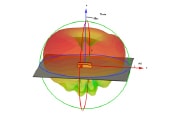
a) TE Gar multi-port antenna placed on 1x1m Ideal Ground Plane
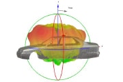
b) Radiation pattern of Gar antenna placed on the roof of the vehicle
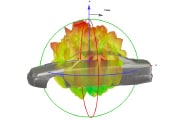
c) GAR antenna placed inside the vehicle
KEY CONNECTED TRANSPORTATION APPLICATIONS

Construction Equipment
Keep heavy equipment connected across demanding jobsites with solutions designed to support asset visibility, machine diagnostics, and remote communications.

Agriculture Equipment
Enable precision farming with reliable connectivity for positioning, equipment communications, and data exchange across connected agricultural systems.

Fleet Telematics
Maintain visibility across vehicles, drivers, and assets with connectivity solutions designed to support tracking, routing, and operational monitoring.
The above examples represent potential connectivity use cases and do not imply guaranteed performance across all system architectures.
ANTENNA SOLUTIONS TO EVALUATE
Multi-Port Vehicular Antenna Platforms
FP40 ultra, vehicle antennas provide an all-in-one solution compatible with LTE/5G, Wi-Fi, GNSS and Bluetooth technologies in high bandwidth mobile connectivity applications.
The product family includes multi-port solutions with up to 14-ports, along with a range of connector options to support integration with many vehicular gateways and routers (compatibility depends on system design and configuration).
EXPLORE MORE IN SMART TRANSPORTATION



TE, TE Connectivity, TE connectivity (logo), and EVERY CONNECTION COUNTS are trademarks owned or licensed by the TE Connectivity plc family ofcompanies. Other product names, logos, and company names mentioned herein may be trademarks of their respective owners.While TE has made every reasonable effort to ensure the accuracy of the information in this document, TE does not guarantee that it is error-free, nordoes TE make any other representation, warranty or guarantee that the information is accurate, complete, correct, reliable or current. TE reserves theright to make any adjustments to the information contained herein at any time without notice. TE EXPRESSLY DISCLAIMS ALL IMPLIED WARRANTIES REGARDING THE INFORMATION CONTAINED HEREIN, INCLUDING, BUT NOT LIMITED TO, ANY IMPLIED WARRANTIES OF MERCHANTABILITY ORFITNESS FOR A PARTICULAR PURPOSE. In no event will TE be liable for any direct, indirect, incidental, special or consequential damages arising from or related to recipient’s use of the information. It is the sole responsibility of recipient of this information to verify the results of this information using their engineering and product environment. Recipient assumes any and all risks associated with the use of the information. Antenna performance may vary. TE is a component manufacturer, and customer and/or end-user is responsible for all end-use compliance and regulatory requirements, as well as suitability for end use determinations (including determining suitability of any mounting/adhesive solution). These marketing materials do not constitute an offer or agreement of sale, and TE Connectivity shall be bound by and subject to only those terms and conditions set forth in a written agreement referencing specific products ands igned by an authorized representative of TE.