White Paper
Predictive Maintenance with Vibration Sensors
Learn more about how vibration sensors are used in predictive maintenance applications and how to choose the right technology.
INTRODUCTION
Driven by increased automation, demand is rising on high-volume, smaller systems such as machine spindles, conveyor belts, sorting tables, or machine tools which require better predictive maintenance.
Machine downtime in these applications is a critical consideration in terms of customer experience and profitability. In the past, accelerometers were primarily used for condition monitoring of heavy, high end machinery such as windmills, industrial pumps, compressors and HVAC systems. However, we see an increasing demand for high volume and smaller machinery, driven by digital industrial transformation. This white paper will compare different technologies of accelerometers in industrial condition monitoring.

CRITICAL FACTORS
For industrial condition monitoring and predictive maintenance applications the following vibration specification parameters are considered critical to ensure long-term, reliable, stable and accurate performance.
- Wide Frequency Response
- Measurement Resolution and Dynamic Range
- Long-Term Stability with Minimum Drift
- Operating Temperature Range
- Packaging Options and Ease of Installation
- Sensor Output Options
Wide Frequency Response
In order to detect all possible failure modes of machinery, the frequency response of the accelerometer should be 40 to 50 times the shaft RPM (Revolutions Per Minute) for bearing monitoring. For fans and gearboxes, the minimum upper limit of the accelerometer should be 4 to 5 times the blade passing frequency. The lower frequency limit is less critical, depending on machinery; rarely is a frequency <2Hz required.
Measurement Resolution and Dynamic Range
The measurement resolution of the vibration sensor is a function of the amplitude of the output signal to the broadband noise of the onboard electronics. An accelerometer with superior signal output will allow the measurement of smaller vibration levels in the machinery. The ability to measure lower vibration amplitude enables the end user to predict a fault much earlier than a sensor with a lower dynamic range.
There are other factors that will influence the measurement resolution such environmental conditions, EMI/RFI (Electromagnetic and Radio Frequency) Interference, DAQ (Define Data Acquisition) interface, and cable length so all factors need to be considered for the chosen installation.
As a general rule, the output signal should be 10x higher than the noise level of the sensor for the output to be a reliable measurement.
A simple equation for measurement resolution is as follows;
RESOLUTION (g’s) = BROADBAND NOISE (V) / SENSOR SENSITIVITY (V/g)
Long-Term Stability
Long-term drift is a shift in the sensitivity and/or zero output measurement (zero output drift applies to MEMS sensors only). A shift in the sensitivity of the accelerometer could trigger a false alarm over time in the monitoring application. A shift in the zero output measurement will also have same effect of potentially causing a false alarm indication. Since Piezoelectric sensors do not have a DC response, they are not susceptible to zero drift, only sensitivity drift. MEMS VC sensor can have both zero and sensitivity drift over time.
In the following section, we will review two different types of technologies that are offered for condition monitoring applications.
PIEZOELECTRIC VIBRATION SENSORS
Piezoelectric (PE) accelerometers incorporate piezoelectric crystals that are self-generating and provide a signal when stressed by external excitation such as vibrating machinery.
Most piezoelectric sensors are based on Lead Zirconate Titanate ceramics (PZT) which are poled to align the dipoles and make the crystals piezoelectric. PZT crystals are ideal for condition monitoring applications since they offer wide temperature range, broad dynamic range, and wide frequency bandwidth (usable to >20kHz).
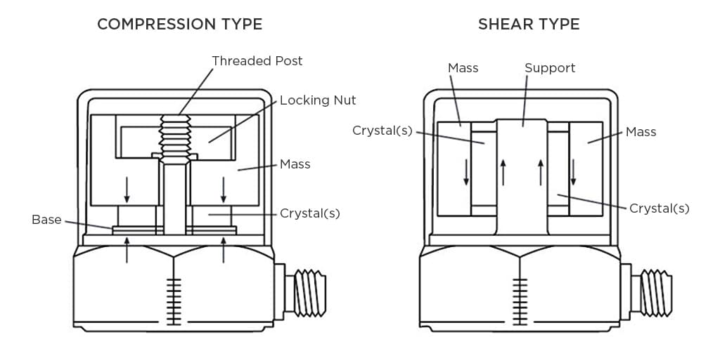
There are basically two main types of PE accelerometer designs available: Compression Mode and Shear Mode (Flexure Mode is a rarely used alternative).
Compression Mode designs are assembled by stressing the piezo-electric crystal in compression by loading a mass on top of the crystal and applying a preload force. These designs are outdated and becoming less popular due to performance limitations. The constructions are susceptible to mounting base strain and have higher thermal drifts.
Shear Mode designs typically have an annular shear crystal and annular mass that is secured to a support post. This design has superior performance compared to compression mode designs in that it is base isolated and much less susceptible to thermal stresses ensuring improved stability. Most condition monitoring accelerometer designs offered today are shear mode and should be the choice of design for most condition monitoring installations.
VARIABLE CAPACITANCE VIBRATION SENSORS
Variable Capacitance (VC) sensors derive the acceleration measurement from a change in capacitance of a seismic mass moving between two parallel capacitor plates. The change in capacitance is directly proportional to the applied acceleration. VC accelerometers require an IC to be closely coupled to the sensing element to convert the very small capacitance changes into a voltage output. This conversion process often results in poor signal to noise ratio and limited dynamic range
The VC sensors are typically manufactured from silicon wafers and are fabricated into miniature MEMS (Micro-Electro-Mechanical-Systems) chips.
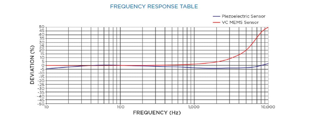
Frequency Response Table
TECHNOLOGY COMPARISON CHART
For industrial condition monitoring and predictive maintenance applications the following vibration specification parameters are considered critical to ensure long term reliable, stable and accurate performance.
- Wide Frequency Response
- Measurement Resolution and Dynamic Range
- Long Term Stability with Minimum Drift
- Operating Temperature Range
- Packaging Options and Ease of Installation
- Sensor Output Options
In the following paragraphs, these critical performance specifications were compared for typical piezo-electric condition monitoring accelerometer and a wide bandwidth MEMS variable capacitance accelerometer also marketed for condition monitoring applications. Both accelerometers had a FS (Full Scale) range of ±50g.
Frequency Response
The frequency response of the two accelerometers were tested on a SPEKTRA GmbH CS18 HF high frequency calibration shaker with a range of 5Hz to 20KHz. The sensors were securely mounted to ensure accurate results over the full test range. Three sensors of each technology, PE and MEMS VC, were tested to ensure the results were consistent.
The results of the testing are illustrated here. A maximum ±1dB amplitude deviation is assumed as the usable bandwidth although a tighter deviation of ±5% is often used for bandwidth tolerance. The data indicates that the VC MEMS sensor has a usable bandwidth up to 3KHz while the Piezoelectric sensor has a usable bandwidth >10KHz (this particular PE sensor was within specification up to 14KHz).
It is worth noting that the low frequency cut-off for the PE sensor was at 2Hz while the MEMS sensor has a response down to 0Hz since it is a DC response device
Measurement Resolution and Dynamic Range
To determine the measurement resolution and dynamic range of the piezo-electric and VC MEMS sensors, the samples were tested in a noise isolated chamber with state-of-the-art measurement equipment capable of micro-g measurement resolution. The units were installed in same chamber and tested at the same time to eliminate any errors from outside environment interference.
The measurements were conducted at four distinct bandwidth settings and the residual noise was measured at each setting. The results are detailed in table below
Residual Noise Comparison at Various Bandwidth
| Model | 0.03-300Hz µV-rms | 0.03-1KHz µV-rms | 0.03-3KHz µV-rms | 0.03-10KHz µV-rms |
|---|---|---|---|---|
PE #1 |
27.2 |
30.8 |
39.5 |
57.6 |
PE #2 |
25.1 |
31.7 |
38.6 |
56.3 |
MEMS #1 |
377.6 |
405.2 |
412.7 |
498.2 |
MEMS #2 |
415.7 |
430.2 |
453.9 |
532.1 |
The measurement resolution and dynamic range were calculated based on a 0.03-10KHz bandwidth and are detailed below. The resolution of the PE sensors is ~9x better than the VC MEMS sensors. This results in a significantly better dynamic range which enables end user to detect potential problems at a much earlier stage.
Measurement Resolution Comparison
| Resolution | Residual Noise | Spectral Noise | Dynamic Range | Resolution | |
|---|---|---|---|---|---|
Model |
mg-rms |
µV-rms |
µg-rms/√Hz |
dB |
bit |
PE #1 |
1.4 |
57.6 |
14.4 |
88 |
14.6 |
PE #2 |
1.4 |
56.3 |
14.1 |
88 |
14.6 |
MEMS #1 |
12.5 |
498.2 |
124.6 |
69 |
11.5 |
MEMS #2 |
13.3 |
532.1 |
133.0 |
68 |
11.4 |
Long-Term Stability with Minimum Drift
The long-term stability of PE sensors is well known with over 30 years field installations. Piezo-electric crystals are inherently stable and have shown to have excellent stability over time. The long-term drift parameters will also depend on the crystal formulation used so an actual value would be difficult to present. Quartz has the best long-term stability of any PE accelerometer but it is rarely used in condition monitoring applications due to limited output and cost. PZT (Lead-Zirconate-Titanate) crystals are the most common crystals used in PE accelerometers and are increasingly becoming the choice of crystal for most applications.
Variable Capacitance MEMS accelerometers also have wide specification limits for long-term drift depending on the MEMS design structure. A bulk micromachined MEMS sensor will have the best long-term drift but will also be significantly more expensive and typically only used in inertial applications. For condition monitoring, MEMS vendors are offering a surface micromachined VC MEMS sensors which are much less expensive but the end user will sacrifice measurement resolution and long-term stability. The MEMS structure of surface micromachined designs are less stable than the bulk micromachined MEMS sensors.
Operating Temperature Range
The operating temperature range of PE and VC MEMS accelerometers are comparable and both are suitable for the typical environment of condition monitoring applications which would span from -40°C to +125°C. In certain extreme installations a higher temperature range sensor may be required where a charge mode piezo-electric sensor would be the recommended choice. Charge mode PE accelerometers which do not include the onboard charge converter circuit, can be used to temperatures exceeding+700°C.
Packaging Options and Ease of Installation
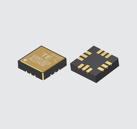
For embedded condition monitoring installations of smaller machinery, the size and mounting options can become an important factor in choosing an accelerometer. Larger machinery typically used an externally TO-5 stud mounted accelerometer but for machinery with smaller bearings and rotating shafts, it will be necessary to use an embedded or miniature accelerometer.
Most VC MEMS accelerometers are offered in a SMT mount package which is ideal for high volume PCBA assembly. The VC MEMS sensors are also offered in very small packages which enables more packaging options.
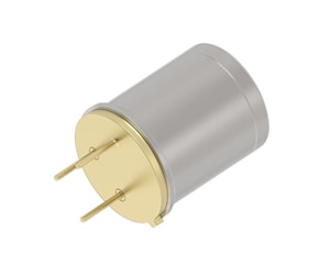
PE accelerometers come in various configurations. The SMT mount version are available, similar to VC MEMS, but the size of the SMT package is typically larger than VC MEMS designs. PE accelerometers are also offered in rugged TO-5 can packages with a stainless-steel housing. These designs allow for direct mounting to bearing housings or embedded installations. The pictures below illustrate some options offered for PE sensors.

Sensor Output Options
Depending on installation and application, a choice of sensor output signal options may be necessary. Most current predictive maintenance installations require an analog signal from the sensor so the end user can decide on which parameters to monitor for particular machinery. Typically, the signal output is driven by the DAQ or PLC interface and an analog output (±2V or ±5V) is the most common choice. However, for installations requiring long cable lengths, loop powered 4-20mA sensors are also common. For future digital factories and Industry 4.0, the need for digital output signals will become more common as will smart sensors with on board microprocessors that can make immediate maintenance decision for the end user.
These output signal options will be available in both PE and VC MEMS sensors. Both technologies would have the capability to provide these functions.
Summary Comparison Table
All or some of the performance parameters discussed in the previous paragraphs will help the customer make an intelligent decision on the technology chosen for the condition monitoring installation. The table below provides a quick summary.
| Key Parameter | Piezoelectric | MEMS VC |
|---|---|---|
Wide Frequency Response |
X |
|
Long Term Signal Stability |
X |
|
Dynamic Range |
X |
|
Operating Temp Range |
X |
X |
Packaging Options |
X |
X |
Ease of Installation |
X |
X |
Sensor Output Options |
X |
X |
CONCLUSION
We have seen different technological features comparing MEMS and PE accelerometers. Both technologies are advantageous depending on the end application. In our case for industrial condition monitoring and predictive maintenance applications, piezoelectric sensors are the obvious choice, thanks to its proven technologies they stay reliable for long term stability. With its wide frequency response, the embedded PE accelerometers are ideal from low to high speed machinery, they also offer a better signal resolution for earlier failure detection.
TE Connectivity (TE) is one of the largest sensor companies worldwide, with innovative sensor solutions that help customers transform concepts into smart, connected creations. Learn more about our broad accelerometer portfolio here.
While condition monitoring has been around for years, it is evolving with the Internet of Things (IoT). Watch this webinar to learn how the IoT is evolving, how condition monitoring sensors are enabling this shift, and the value of recognizing sensors as key components of condition monitoring applications.
-

Reducing Costly Downtime: Accelerometers Transform Machine Maintenance (English)
-
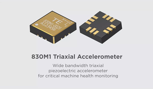
830M1 Triaxial Accelerometer (English)