Load Cell Fundamentals
Explore the fundamental concepts that are important to understand load cells and discuss critical performance characteristics and environmental considerations.
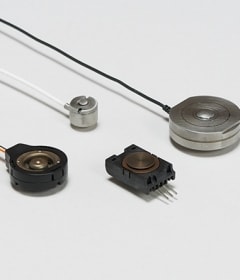
Load cell fundamentals cover basic principles that influence sensor selection and application. Key considerations include whether the load cell measures compressive or tensile forces, whether it is designed for static loads that change slowly or dynamic loads that with rapid fluctuations, and whether it supports single-axis or multi-axis configurations. Understanding these core concepts is essential for ensuring accurate and reliable performance across all applications.
Compression vs. Tension in Load Cells
Load cells measure force, and the type of force (compression or tension) drives design, installation and application choices.
Compression load cells measure force when the load pushes toward them causing a compressive force. This is typical in truck and industrial platform or tank scales where the load cell is mounted under a structure or platform.
Advantages:
- Simple installation for static loads
- High-capacity options are available
Error risks:
- Uneven load distribution
Tension load cells measure force when the load pulls away from the load cell causing a tensile force. Crane scales monitoring and cable tension measurement are common applications for these load cells where the load cell is in line with the load path.
Advantages:
- Suited for suspended loads
- Can measure dynamic forces in lifting systems
Error risks:
- Side loading or misalignment
Combination load cells can measure both tension and compression. These sensors are useful in testing machines or materials.
Load cells in torque measurement are more complicated because instead of measuring a single axial force, torque sensors (rotary load cells) measure shear strain due to twisting. When bonded to a shaft at 45° angles, one gauge experiences tension while the opposite diagonal undergoes compression. In this case, the strain bridge uses opposing strains to produce a differential signal proportional to the torque.
Selecting the correct load cell form factor begins with identifying the type of force required by the application. Each force type favors specific geometries and sensing technologies that influence accuracy, installation complexity, and suitability for static or dynamic loads.

Static vs. Dynamic Measurements
Static measurements apply to loads that remain constant or change very slowly over time. A truck scale and a load cell that measures a stationary tank are examples. Conversely, dynamic measurements involve forces that change rapidly due to motion, vibration or impact.
Applications that often measure these dynamic loads are crash testing and robotic monitoring. Distinguishing between static and dynamic conditions influences load cell selection, signal conditioning and accuracy requirements. Static applications prioritize long-term stability and minimal creep, while dynamic applications demand fast response, high natural frequency and effective noise filtering to accurately capture transient forces.
Dynamic load applications demand more than just high-speed sensing, they also require careful attention to latency and mechanical compliance. Latency is the delay between a force change and the sensor’s output, which can affect real-time control and peak detection in fast moving systems. Mechanical compliance refers to flexibility in the load path that can absorb energy, slow settling time, and distort measurements under rapid load changes. Minimizing both is essential for achieving accurate, high-bandwidth performance.
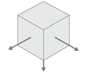
Single-Axis vs. Multi-Axis Load Cells
Load cells are designed to measure force, but depending on the complexity of the application, single-axis or multi-axis sensors may be required. Understanding the differences between these and knowing when to use one or the other has a big impact on implementation success.
| Feature | Single-Axis | Multi-Axis |
|---|---|---|
| Measurement | One axis (tension or compression) | Multiple axes (X,Y,Z) and sometimes torque |
| Performance Priority | Accuracy in a well-defined load path | Full force vector analysis; minimize off-axis errors |
| When to Choose | Predictable load direction; cost-sensitive applications | Complex systems; robotics; aerospace |
| Advantages | Simple installation; low cost; small footprint | Captures complete load profile; reduces off-axis errors |
| Limitations | Sensitive to off-axis errors; cannot measureme moments | Higher cost; complex calibration and signal processing |
| Calibration Complexity | Basic; factory or field calibration | Advanced; multi-point calibration required |
| Cost Impact | Low to moderate | High |
| Typical Applications | Weighing systems; cranes; material testing | Robotic actuators; aerospace structural monitoring; biomechanics |
Performance characteristics describe how effectively a load cell performs under real-world conditions and include several key factors. Accuracy and precision determine measurement quality, while response time affects how quickly the sensor reacts to load changes. Calibration and drift influence long-term measurement stability, while lifespan and reliability reflect the durability of load cells under mechanical and environmental stress. Size and weight constraints also impact integration, especially in compact or mobile systems. Understanding these characteristics helps to define both technical and operational requirements for successful implementation.
Accuracy & Precision
Accuracy and Precision
Accuracy and precision are both essential metrics for load cell performance, but they represent different dimensions of measurement quality.
- Accuracy describes the amount of error between the measured output and the actual value of the applied load.
- Precision refers to the repeatability of measurements under identical conditions, regardless of how close they are to the true value.
Example:
- If a 100 lb force is applied and the load cell reads 99.9 lbs, this would be considered high accuracy.
- Repeated measurements range from 100.1 lbs to 99.6 lbs, this would be consdiered high accuracy and precision.
- Repeated measurements range from 101.5 lbs to 98.0 lbs, this would be considered neither accurate nor precise.
| Specification | Typical Value | Description | Impact on Application |
|---|---|---|---|
| Accuracy | ±1.0% FS | Deviation from the true value of the applied load. | Determines suitability for precision tasks like closing, weighing, or force verification. |
| Combined Linearity & Hysteresis | ±1.0% FS | Combined error from non-linearity and hysteresis. | Affects repeatability and consistency in cyclic or bidirectional loading environments. |
| Zero Shift (per °C) | ±0.05% FS/°C | Change in zero output due to temperature variation. | Critical for outdoor or thermally variable installations; impacts baseline stability. |
| Sensitivity Shift (per °C) | ±0.05% FS/°C | Change in sensitivity due to temperature variation. | Influences scaling accuracy in fluctuating environments; may require compensation. |
Sources of Error:
Several factors (mechanical, environmental, and electrical) can degrade load cell accuracy and precision, each requiring targeted mitigation.
- Mechanical inconsistencies like overloading, side loading, and poor mounting can distort strain gauge readings or introduce stress concentrations. Creep, gradual output drift under constant load is another issue, especially in systems lacking proper compensation.
- Environmental influence such as temperature fluctuations, humidity and electromagnetic interference can degrade performance.
- Signal noise, cable resistance and unstable excitation voltages impact measurement reliability.
From a calibration perspective, load cells may exhibit non-linearity, hysteresis, zero balance shifts and resolution limits. These affect consistency and accuracy when translating force into electrical signals. Proper installation, shielding, and regular calibration are key to minimizing errors and providing reliable performance regardless of the application.
Technology Impact
To understand how these errors can manifest across technologies, we compare the accuracy and precision characteristics of four common load cell technologies, along with key factors that influence their performance in various operating conditions.
| Technology | Accuracy | Precision | Influencing Factors |
|---|---|---|---|
| Strain Gauge | Moderate | High | Adhesive creep; temperature drift; hysteresis; mechanical fatigue; calibration frequency |
| Capacitive | High | Moderate to high | Dielectric stability; humidity; contamination; EMI shielding; mechanical alignment |
| Piezoresistive | High | Very high | Packaging; encapsulation; temperature sensitivity; mechanical alignment |
| Hydraulic | Low to moderate | Low to moderate | Fluid viscosity changes; mechanical wear; seal integrity; ambient pressure fluctuations |
Form Factor Influence
Beyond sensing technology, the physical size and geometry of a load cell can significantly impact its performance. Miniature load cells, while ideal for space-constrained applications, are more susceptible to mounting errors, off-axis loading and thermal effects. In contrast, larger load cells offer greater stability and resistance to environmental influences but may present challenges with dynamic response and installation complexity. Regardless of size, the geometry and mounting configuration, such as surface flatness, load alignment and load path, critically affect how strain is measured. This makes proper installation and design integration essential for reliable performance.
Response Time
The speed at which a load cell reacts to changes in applied force—known as response time—is a critical performance metric in both industrial and precision applications. It determines not only how quickly data is captured, but how accurately that data reflects real-world dynamics. In high-speed packaging, for example, a slow response may result in missed weight readings. In safety-critical systems like cranes or pressure vessels, delayed detection of overloads can compromise operator safety or regulatory compliance.
Response time is characterized by three interrelated parameters:
- Rise time: the time required for the signal to reach a specified percentage of its final value once a load is applied.
- Settling time: the duration required for the signal to stabilize within a defined tolerance range after a disturbance.
- Bandwidth: the frequency range (in Hz) over which the load cell can accurately respond to dynamic inputs. A higher bandwidth enables faster response and better tracking of transient or oscillating forces.
These parameters are often specified in global standards such as EN 45501, OIML R60, and ASTM E74, which define performance thresholds and test methods for dynamic weighing and force measurement.
Effects of Technology on Response Time
Comparison of the typical response times across four common load cell types, highlighting their relative speed and suitability for various applications.
| Technology | Typical Response Time | Dynamic Performance | Notes |
|---|---|---|---|
| Strain Gauge | 10 - 100ms | Moderate | Highly dependent on signal conditioning and mechanical damping |
| Capacitive | <10ms | Fast | Rapid electrical response; sensitive to environmental noise |
| Piezoresistive | <5ms | Very fast | Excellent for dynamic measurements; minimal lag |
| Hydraulic | >100ms | Slow | Fluid inertia and damping slow response time; suited for static loads |
Physical Factors Affecting Load Cell Response Time
The mechanical behavior of the load cell and its installation have significant impact on response time. The following table summarizes key physical factors that impact response time.
| Factor | Impact on Response Time | Effect Description | Engineering Implication |
|---|---|---|---|
| Mechanical Damping | Adding mechanical damping may slow response | Absorbs energy and delays mechanical settling time, reducing oscillations and overshoot | Use minimal damping for dynamic loads. Apply damping for stability in static applications |
| Stiffness | Increased stiffness speeds response | Higher stiffness speeds settling time and can reduce structural lag | Increase stiffness for improved bandwidth and reducing oscillation |
| Mass | Increased mass slows response | Greater inertia resists rapid motion or force changes | Reducing mass improves dynamic response but can compromise durability or overload capacity |
| Mounting & Packaging | Flexible, vibrating mounting destabilizes response | Rigid, aligned mounting improves strain transmission; soft or misaligned setups delay it | Ensure rigid, vibration-isolated mounting; avoid flexible or thermally unstable interfaces |
| Load Dynamics | Load dynamics determines speed requirements | Fast changing loads require rapid signal stabilization | Match sensor bandwidth to expected load rate; avoid over-filtering in dynamic applications |
| Environment | Typically slows response | Temperature drift, vibration, and contamination can distort or delay signal stabilization | Requires compensation (e.g. shielding, temperature sensors) to maintain reliable response |
| Form Factor | Larger form factors slow response time | Larger or more compliant geometries dampen or delay signal transmission | Use compact, symmetric designs for faster mechanical response; avoid excessive overhangs |
Electrical Factors Affecting Load Cell Response Time
Key electrical factors that influence load cell response time. These elements affect how quickly and reliably a load cell can detect and transmit changes in force with direct implications for system design and performance in dynamic applications.
| Factor | Impact on Response Time | Effect Description | Engineering Implication |
|---|---|---|---|
| Sensor Material Properties | Sets baseline speed | Determines how quickly the sensing element reacts to strain or pressure | Choose fast-reacting materials; avoid fluid-based substances |
| Signal Conditioning Circuitry | Can increase or descrease response | Filters, amplifiers, and ADCs can introduce latency or enhance clarity | Optimize for bandwidth vs noise; avoid excessive filtering in dynamic systems |
| Environmental Concerns | Can destabilize response | Temperature, humidity, and EMI can cause drift or jitter | Shield electronics; use temperature compensation and conformal coatings |
| Electrical Noise Sensitivity | Oversensitive load cells can slow or corrupt signals | Noise can mask true signal changes or delay detection | Use differential inputs, shielding, and low-noise amplifiers |
Calibration & Drift
Calibration Methods
Load cell calibration can be performed either at the factory or in the field; each method serves different purposes.
- Factory calibration: conducted under controlled conditions using traceable standards and precision equipment. This provides a reliable baseline for accuracy and often embeds calibration data into digital systems. However, it doesn’t account for installation-specific influences like mounting stress or environmental variability.
- Field calibration: performed on site after installation to adjust for real-world conditions. It may involve known weights, shunt calibration, or software-based tuning, and is essential for maintaining accuracy over time, especially after overload events or environmental shifts.
While factory calibration offers high precision and traceability, field calibration can provide reliable performance at the installation site. Many applications benefit from a hybrid approach, relying on factory calibration for initial setup and using field calibration for ongoing verification and adjustment. The choice depends on the application’s sensitivity to environmental factors, regulatory requirements and the need for dynamic recalibration.
Drift Over Time
Gradual deviations in load cell output can compromise both measurement accuracy and calibration stability. It may result from thermal cycling, material fatigue, or electronic aging. Each of these introduces subtle but cumulative changes in zero balance, sensitivity, or linearity. For example, repeated thermal fluctuations can alter strain gauge resistance, while long-term mechanical stress may cause creep or microstructural shifts in the sensing element. Electronic components such as amplifiers and ADC’s may also degrade, affecting signal fidelity. These effects are often slow to develop and difficult to detect without periodic recalibration. This graph illustrates how drift mechanisms (thermal, mechanical, and electronic) accumulate over time in the absence of recalibration.
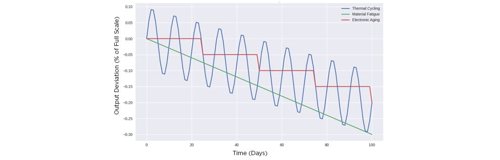
Load cell drift over time by influence type
Technology Comparison
Calibration and drift by load cell technology
The following table highlights the relative impact of calibration stability and drift susceptibility across common load cell technologies. It identifies which influences are most prevalent for each type and recommends field calibration where appropriate. The goal is to support informed selection and maintenance strategies based on the application demands and long-term performance goals.
| Technology | Calibration Stability | Drift Susceptibility | Dominant Drift Influence | Field Calibration Recommendation |
|---|---|---|---|---|
| Strain Gauge | Moderate | Moderate | Thermal cycling; fatigue | Yes - installation sensitive |
| Capacitive | High | Moderate | Thermal effects; electromagnetic interference | Recommended for noise tuning |
| Piezoresistive | High | Low | Electronic aging | Rarely - stable electronics |
| Hydraulic | Low | High | Mechanical creep; fluid aging | Yes - frequent recalibration |
Best Practices
To ensure long-term accuracy and reliability, best practices for managing calibration and drift begin with selecting the appropriate calibration method based on the application and technology. Factory calibration provides baseline precision, while field calibration accounts for installation-specific influences. In dynamic or high-risk applications, regular recalibration intervals should be based on the load frequency, environmental exposure, and regulatory requirements.
Where thermal cycling, vibration, or electromagnetic interference are present, environmental compensation, can significantly reduce drift. For safety-critical systems or harsh operating conditions, redundant sensing (e.g. dual load cells or parallel measurement channels) adds fault tolerance and early detection of calibration drift or sensor failure. Together, these strategies form a robust framework for sustaining measurement integrity over time.
Lifespan & Reliability
Understanding the factors that influence load cell lifespan and reliability is useful for selecting the right technology and maintaining long term performance. This section examines how mechanical fatigue, environmental stress, design
architecture, and failure modes interact across different load cell types, providing a foundation for informed maintenance and specification decisions
Mechanical Fatigue and Environmental Stress
Mechanical fatigue and environmental stress are critical factors that directly affect the lifespan and reliability of load cells. Repeated loading cycles, especially those that approach the cell’s rated capacity, can induce microstructural changes in the sensing element. This may lead to gradual loss of sensitivity or permanent deformation. The effect of this fatigue intensifies in environments with high vibration, shock, or inconsistent loading profiles. At the same time, environmental factors such as temperature fluctuations, humidity, and exposure to corrosive substances can degrade strain gauge adhesives, alter electrical resistance and accelerate aging of electronic components. Over time, these combined influences increase the likelihood of drift, signal instability, or failure. This makes proactive calibration and protective design elements essential for maintaining long-term measurement integrity. These stressors vary in impact depending on the load cell technology used.
Technology Comparison
Lifespan and reliability by load cell technology
This table provides a comparative overview of how different load cell technologies perform over time, especially under mechanical and environmental stress. It highlights expected lifespan, reliability, and other factors offering a practical reference for selecting sensors based on durability and maintenance demands.
| Technology | Typical Lifespan | Reliability in Harsh Conditions | Susceptibility to Drift | Maintenance Needs | Notes on Failure Modes |
|---|---|---|---|---|---|
| Strain Gauge | 5 - 10 years | Moderate | Moderate (thermal, fatigue) | Periodic recalibration | Adhesive degradation, fatigue cracks |
| Capacitive | 10 - 15 years | High | Low - moderate (EMI, temperature) | Occasional tuning | Sensitive to electrical noise |
| Piezoresistive | 10 - 20 years | High | Low (aging electronics) | Minimal | Stable unless exposed to extreme conditions |
| Hydraulic | 5 - 10 years | Low to moderate | High (fluid aging, creep) | Frequent calibration | Seal wear, fluid degradation |
Failure Modes
Load cells are subject to several failure modes that can compromise measurement accuracy and system reliability over time.
- Wire breakage is often caused by vibration, flexing or poor strain relief, which can lead to intermittent signals or complete loss of output, especially in installations with frequent movement or thermal expansion.
- Seal degradation is common in hydraulic and environmentally exposed load cells, seal leaks allow moisture or contaminants to enter the sensor housing. This accelerates electrical instability and corrosion.
- Diaphragm fatigue is typically found in strain gauge and piezoresistive designs. Diaphragm fatigue results from repeated cycling that gradually weakens the sensing element. Fatigue can lead to drift, hysteresis, or rupture.
Identifying these failure modes early through routine inspection and signal monitoring is essential for maintaining safe and accurate load measurements. Beyond material and electrical design, the physical configuration also plays a key role in long-term reliability.
Form Factor Considerations
Form factor plays a critical role in determining the lifespan and reliability of load cells, particularly when encountering space constraints, dynamic loading or harsh conditions. Compact designs may offer installation flexibility but often sacrifice mechanical robustness, making them more susceptible to fatigue or thermal stress. Larger form factors allow for thicker diaphragms, better strain distribution, and improved heat dissipation, which can extend service life and reduce drift. Also, the orientation and mounting configuration (compression vs tension; flange vs threads) can influence how well the load cell resists vibration, shock, and seal degradation.
Thin-film sensors, while compact and responsive, may be more vulnerable to surface damage and fatigue than bulk sensor designs, which offer greater mechanical resilience. Similarly, embedded sensing elements provide better protection against environmental stressors compared to exposed designs, which are more accessible but prone to contamination and wear.
Selecting a form factor that aligns with both mechanical demands and environmental exposure is essential for maximizing long-term performance and minimizing failure risk.
Constraints
Performance integration and application suitability are directly affected by the size and weight of the components. In compact systems, minimizing the load cell’s footprint requires careful optimization of strain gauge placement, signal conditioning and mechanical geometry to preserve sensitivity and linearity. Smaller load cells are more vulnerable to complications from off-axis loading and thermal drift. This requires enhanced compensation strategies and precision machining. Weight reduction is equally critical in dynamic or mobile applications where increased mass can increase inertia, reduce responsiveness, or distort force transmission. Engineers must balance these constraints against structural integrity, ensuring that size and weight limitations do not compromise overload protection or long-term stability. The challenge ultimately lies in designing load cells that deliver accurate, repeatable measurements while conforming to the spatial and mass constraints of the system.
Impact on Miniaturization
These trade-offs between size, weight and performance demand careful consideration by engineers developing miniaturized load cells for medical and aerospace applications. These sectors prioritize compact and lightweight components to meet strict spatial and operational constraints, but doing so can introduce challenges in accuracy, durability, and integration. For example:
- Medical devices: Implantable or handheld diagnostic devices require ultra-miniature load cells that maintain high sensitivity. However, miniaturization can reduce strain gauge surface area, increasing noise and limiting resolution.
- Aerospace systems: Weight savings are critical for fuel efficiency and payload maximization, yet smaller load cells may suffer from reduced overload capacity and increased impacts from vibration and thermal cycling.
- Material selection: Lightweight alloys or composites may reduce mass but introduce challenges in fatigue resistance or long-term stability under cyclic loads.
- Signal integrity: Shorter lead lengths and tighter packaging can increase electromagnetic interference, requiring advanced shielding or signal conditioning
| Sector | Size Constraints | Weight Constraints | Performance Trade-offs | Mitigation Strategies |
|---|---|---|---|---|
| Medical | Must fit within handheld or implantable devices | Minimal to avoid patient discomfort or device bulk | Reduced strain gauge area, increased noise, limited resolution | Use of MEMS technology, advanced signal conditioning, precision machining |
| Aerospace | Must integrate into compact, multi-functional assemblies | Critical for fuel efficiency and payload optimization | Lower overload capacity, increased vibration sensitivity, thermal drift | Lightweight alloys, vibration damping, thermal compensation algorithms |
These trade-offs must be strategically balanced to ensure reliable force measurement without compromising mission-critical performance.
Technology Comparison
Size & weight constraints
Different load cell technologies respond uniquely to size and weight constraints, influencing their suitability for specific applications. The following table compares how design trade-offs—such as miniaturization limits, structural demands, and integration complexity—shape performance across technologies. Understanding these distinctions helps engineers select the most appropriate sensing solution for environments where space and mass are at a premium.
| Technology | Size Constraints | Weight Constraints | Typical Applications |
|---|---|---|---|
| Strain Gauge | Moderate miniaturization possible; limited by gauge placement and bonding | Lightweight designs feasible; structural support still needed | Industrial scales, aerospace, robotics |
| Capacitive | Highly adaptable to miniaturization; ideal for MEMS and micro-scale devices | Extremely lightweight; suitable for portable and wearable tech | Medical devices, consumer electronics |
| Piezoresistive | Compact integration possible; sensitive to packaging stress | Lightweight but requires stable housing to reduce drift | Biomedical sensors, automotive pressure sensing |
| Hydraulic | Bulky due to fluid chambers and mechanical linkages | Heavier by nature; not ideal for mobile or weight-sensitive systems | Heavy-duty industrial and structural monitoring |
Form Factor Comparison
Size & weight constraints
The following table provides a visual breakdown of how common load cell form factors such as pancake, S-beam, canister, and tension/compression influence size and weight constraints in design and applications.
| Technology | Size Considerations | Weight Considerations | Typical Use Cases |
|---|---|---|---|
| Pancake (Low Profile) | Wide diameter with minimal height; ideal for tight vertical spaces | Generally lightweight but may require mounting plates for stability | Aerospace, robotics, industrial automation |
| S-Beam | Compact and symmetrical; easy to integrate into small assemblies | Lightweight and versatile; suitable for portable systems | Medical devices, material testing, small-scale tension / compression |
| Canister | Taller cylindrical profile; requires more vertical clearance | Heavier due to robust housing; optimized for high-capacity loads | Structural monitoring, heavy industrial weighing |
| Tension / Compression | Varies widely; often designed for axial load paths with minimal lateral footprint | Weight depends on capacity; low-profile options available for mobile applications | Crane scales, actuator feedback, aerospace linkages |
Environmental Conditions
Defining environmental requirements is critical to ensuring load cell reliability and safety. Environmental ratings can impact performance, life expectancy and long-term accuracy under real-world conditions. These factors often dictate long-term reliability more than the sensing technology itself. The following subsections outline the most typical considerations.
Temperature Range
It is important to consider the full operating temperature range of the load cell application. Wide temperature swings can cause thermal drift and zero shift, reducing accuracy. Applications such as outdoor weighing or aerospace systems require sensors with temperature compensation orclimate-controlled enclosures.
Ingress Protection (IP Rating)
Moisture, dust, and corrosive chemicals degrade sensor performance and shorten their service life. IP-rated housings and corrosion-resistant materials like stainless steel or anodized aluminum are essential for harsh environments. Hermetic sealing and epoxy encapsulation protect strain gauges and electronics.
The IP rating is a standardized global rating system that indicates the level of protection against dust and water. The rating consists of the letters IP followed by 2 digits. The first digit indicates the level of protection against solid objects.
| Digit | Protection Level Against Solids | Protection Level Against Water |
|---|---|---|
| 0 | None | No Protection |
| 1 | Objects over 50mm (2 inches) | Dripping water (vertical) |
| 2 | Fingers, etc. over 12.5 mm (0.5 inch) | Dripping water (up to 15° angle) |
| 3 | Tools/wires over 2.5 mm (0.1 inch) | Spraying water (up to 60° angle) |
| 4 | Small wires over 1 mm (0.04 inch) | Splashing water (any direction) |
| 5 | Dust-protection (limited ingress) | Water jets |
| 6 | Dust-tight (no ingress) | Powerful water jets |
| 7* | --- | Temporary Immersion (< 30 min) |
| 8* | --- | Continuous Immersion (depth specified) |
| 9* | --- | High-pressure, high temperature water jets |
*Note: only numbers 0-6 apply to the first digit and 0-9 apply to the second digit
Corrosion Resistance
Addressing corrosion resistance is important for durability and reliability of load cells. This is especially important in outdoor environments or in areas where harsh conditions occur. Hermetic sealing, IP rated enclosures, and specialty materials can often provide excellent protection. Material selection is also important to mitigate potential corrosion.
Load Cell Body: The load cell body is typically the most vulnerable element since it is often in direct contact with moisture, chemicals, salt spray, or acidic environments.
- High alloy stainless steel provides high corrosion resistance for the most demanding applications.
- Hard anodized aluminum is often used for lightweight systems that require moderate corrosion resistance.
- Protective coatings or plating can also enhance the durability of load cell body surfaces.
Strain Gauges: Exposure to moisture ingress is a serious risk factor for strain gauges. Corrosion can have a huge impact on the operation of these components.
- Hermetic sealing of the strain gauge cavity can provide a level of protection for strain gauges.
- Epoxy encapsulation can also provide ingress protection.
- Glass-to-metal seals are quite effective for this purpose as well.
Electrical Connectors: Corrosion at connection points due to humidity or chemical exposure can seriously impact sensor relability and accuracy. These risks can be mitigated using with several approaches.
- Shielded cables with waterproof jackets can prevent moisture from invading the connection point.
- IP-rated connecters can be specified for sealed interfaces to minimize the corrosion risk.
Bonding Adhesives: Adhesives used to bond strain gauges to the body can degrade over time presenting a significant risk of corrosion. High-performance bonding adhesives rated for chemical and thermal resistance can be quite effective if their resistance targets harsh environments particular to the application.
Electromagnetic Compatibility (EMC)
Electromagnetic interference can cause signal drift, noise, or failure in sensitive load cell circuits. Protection from electromagnetic interference (EMI), radio frequency interference (RFI) and electrostatic discharge (ESD) are important to consider when selecting load cells. The following measures can improve signal security, extend the load cell life span and confirm compliance with industry standards.
- Shielded cables: Twisted-pair wires with braided or foil shielding, grounded at one end can be effective in preventing interference in signal lines.
- Faraday cage: Metal housings with conductive seals act as a Faraday cage to block external EMI/RFI.
- Filters: Ferrite beads, capacitors, and low-pass filters on signal and power lines suppress high-frequency noise and voltage spikes.
- Grounding: Proper grounding of the load cell body, cable shield and signal processing equipment provides a low-impedance path for stray currents and static discharge.
- ESD protection circuits: TVS (Transient Voltage Suppression) diodes or ESD suppressors on IO lines can significantly reduce the risk of damage from electrostatic discharge.
- Electrical isolation: Optical or transformer-based isolation in signal conditioning modules prevents conducted interference between the load cell and data acquisition systems.
- PCB best practices: Using controlled impedence traces, ground planes and separation of analog/digital paths helps to minimize internal EMI and crosstalk.
Shock and Vibration Resistance
For mobile, automotive, aerospace and industrial machinery applications, the ability to withstand mechanical shocks and vibrations without degrading load cell performance is imperative. In these applications, ruggedized designs or vibration damping features should be implemented where feasible.
Installation & Maintenance
Proper installation and ongoing maintenance are essential for achieving consistent, reliable measurements and extending the lifespan of load cells. This section outlines key considerations for mounting, wiring, calibration, and troubleshooting common issues.
Mounting considerations
- Confirm that the mounting surface is flat, rigid and free of contaminants to prevent uneven stress and off-axis loading.
- Use the correct torque specifications for bolts to avoid distortion of the load cell body.
- Align the load path precisely with the sensor’s axis to minimize measurement errors.
- For dynamic applications, incorporate vibration isolation or damping mounts where necessary.
Wiring and signal conditioning
- Route cables away from sources of electrical noise such as motors or high-tension lines.
- Use shielded, twisted-pair cables to reduce electromagnetic interference (EMI)
- Maintain proper strain relief at cable entry points to prevent wire fatigue.
- Verify grounding and shielding practices to ensure signal integrity.
Calibration Procedures
- Perform factory calibration for baseline accuracy and traceability.
- Conduct field calibration after installation to account for mounting influences and environmental conditions.
- Use certified test weights or shut calibration methods for verification.
- Schedule periodic recalibration based on application demands (e.g. every 6-12 months for static loads, more frequently for dynamic systems).
Common failure modes and troubleshooting
- Wire breakage: Often caused by vibration or poor strain relief. Inspect cables regularly and replace damaged wiring when observed.
- Seal degradation: Moisture ingress can lead to corrosion or signal instability. Check seals and replace them if they are compromised.
- Diaphragm fatigue: Repeated overloads or cyclic stresses can cause drift or failure. Monitor output for signs of hysteresis or creep.
- Signal noise or drift: May results from EMI, temperature fluctuations, or loose connections. Verify shielding, grounding, and connector integrity.
Best practice: Implement routine inspections and maintain a calibration log and record all maintenance activities. Early detection of anomalies can prevent costly downtime and ensure long-term reliability.