The Need for Transient Suppression
This application note has been written in response to the numerous application problems resulting from improper relay coil suppression. The typical symptom is random "tack" welding of the normally-open contacts when switching an inductive load or a lamp load with high inrush current.
When an electromechanical relay is de-energized rapidly by a mechanical switch or semiconductor, the collapsing magnetic field produces a substantial voltage transient in its effort to disperse the stored energy and oppose the sudden change of current flow. A 12VDC relay, for example, may generate a voltage of 1,000 to 1,500 volts during turn-off. With the advent of modern electronic systems, this relatively large voltage transient has created EMI, semiconductor breakdown, and switch wear problems for the design engineer. It has thus become common practice to suppress relay coils with other components which limit the peak voltage to a much smaller level.
Types of Transient Suppression Utilized with Relays
The basic techniques for suppression of transient voltages from relay coils are shown in Figure
- As observed here, the suppression device may be in parallel with the relay coil or in parallel with the switch used to control the relay. It is normally preferred to have the suppression parallel to the coil since it can be located closer to the relay (except in the case of PC board applications where either may be used). When the suppression is in parallel with the relay coil, any of the following may be used.
A. A bilateral transient suppressor diode that is similar in V-I characteristics to two zener diodes connected cathode to cathode (or anode to anode).
B. A reverse-biased rectifier diode in series with a zener diode such that their anodes (or cathodes) are common and the rectifier prevents normal current flow.
C. A metal-oxide-varistor (MOV).
D. A reversed-biased rectifier diode in series with a resistor.
E. A resistor, when conditions permit its use, is often the most economical suppression.
F. A reversed-biased rectifier diode.
G. A resistor-capacitor "snubber". Generally the least economical solution and no longer considered a practical solution.
H. A bifilar wound coil with the second winding used as the suppression device. This is not very practical since it adds significant cost and size to the relay.
Suppression used in parallel with the switching element is likely to be either a zener diode or a resistor-capacitor "snubber." The comments associated with the "parallel to coil" application are also applicable to this circuit.
Suppressor Parallel to Switch
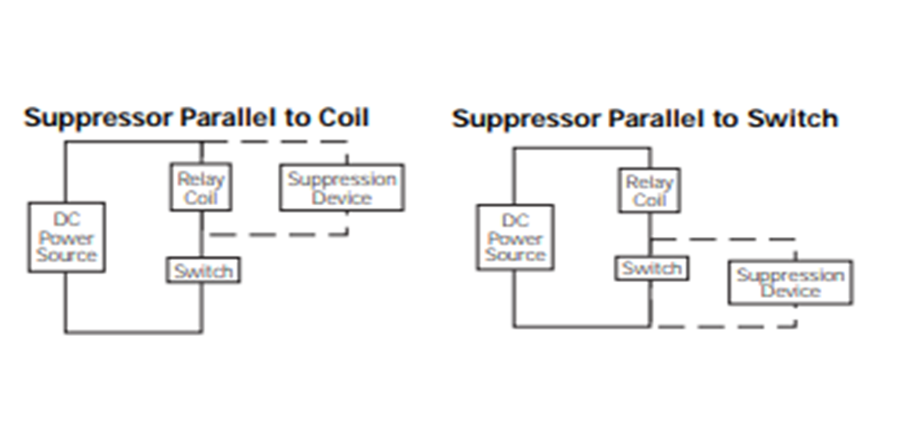
Figure 1. Schematic for Relay Coil Suppression: Suppressor Parallel to Coil, and Suppressor Parallel to Switch
Effects of Coil Suppression on Relay Dynamics and Life
Even though the use of coil suppression is becoming more significant, relays are normally designed without taking the dynamic impact of suppressors into account. The optimum switching life (for normally-open contacts) is therefore obtained with a totally unsuppressed relay and statements of rated electrical life are usually based on this premise. The successful "breaking" of a DC load requires that the relay contacts move to open with a reasonably high speed.
A typical relay will have an accelerating motion of its armature toward the unenergized rest position during drop-out. The velocity of the armature at the instant of contact opening will play a significant role in the relay's ability to avoid "tack welding" by providing adequate force to break any light welds made during the "make" of a high current resistive load (or one with a high in-rush current). It is the velocity of the armature that is most affected by coil suppression. If the suppressor provides a conducting path, thus allowing the stored energy in the relay's magnetic circuit to decay slowly, the armature motion will be retarded and the armature may even temporarily reverse direction. The reversing of direction and re-closing of the contacts (particularly when combined with inductive loads) often leads to random, intermittent "tack welding" of the contacts such that the relay may free itself if operated again or even jarred slightly.
Based upon the impact on armature motion and optimizing for normallyopen contacts, the best suppression method is to use a silicon transient suppressor diode. This suppressor will have the least effect on relay dropout dynamics since the relay transient will be allowed to go to a predetermined voltage level and then permit current to flow with a low impedance. This results in the stored energy being quickly dissipated by the suppressor. Transient suppressor diodes are available as bi-directional components and permit the relay to be non-polarized when installed internally. Note that if a uni-directional transient suppressor is used, a rectifier diode must be placed in series with it to block normal current flow and it has little advantage over the use of a zener diode. The transient suppressor should be selected such that its pulse energy rating exceeds any anticipated transient such as coil turn-off or motor "noise" found in the application.
A metal-oxide-varistor will provide results similar to those of transient suppressor diode, but will have a higher "on-state" impedance and will thus allow a higher voltage to be developed. As an example, a 33 volt transient suppressor diode may have a "clamping" voltage between 30 and 36 volts. In comparison, a 33 volt MOV will likely clamp the relay at 45 to 55 volts (based on a typical automotive relay with 130 mA coil current). When the additional voltage is no problem, an MOV may save cost over the transient suppressor diode and will also provide a non-polarized relay.
The use of a reversed-biased rectifier diode in series with a zener diode will provide the best solution when the relay can be polarized. This suppression is often recommended by Siemens Electromechanical Components (SEC) for use in automotive circuits. The impact on release dynamics is minimal and poses no loss of reliability. This is normally a low-cost method and the only design precaution is to select a zener with an appropriate breakdown voltage and impulse power specifications adequate for the relay in its application. In printed circuit board applications with transistors used as relay drivers, the zener diode can be placed "across" the transistor; that is, for a common emitter circuit, cathode connected to collector and anode connected to the emitter (the series rectifier diode is not used in this type of circuit).
A reversed-biased rectifier in series with a resistor may be used successfully with some relays when maximum load switching capacity is not required. Care must be taken to use a resistor large enough in value to quickly dissipate the relay's stored energy but yet stay within the desired peak voltage transient. The required resistor value may be approximated from the following equation:
R = Vpeak/Icoil
where:
R = resistor value in Ohms
Vpeak = peak transient voltage permitted
Icoil = steady-state relay coil current
The actual voltage peak observed will be lower than calculated by this formula due to energy losses in the resistor. When using this type of suppression it is best to consult the relay manufacturer for recommended values.
A resistor may also be used by itself as a transient suppressor when the additional power dissipation and resulting heat generated by the resistor can be tolerated. In most situations, this will provide the least expensive suppression method (assuming the resistor value can be properly sized to minimize its impact on relay performance). This method is normally recommended by SEC when the application requirements permit.
Many engineers use a rectifier diode alone to provide the transient suppression for relay coils. While this is cost effective and fully eliminates the transient voltage, its impact on relay performance can be devastating. Problems of unexplained, random "tack welding" frequently occur in these systems. In some applications, this problem is merely a minor nuisance or inconvenience and the controller or operator will cycle the relay until the proper response is obtained. In many applications; however, the first occurrence may cause a complete system failure or even present a hazardous situation. It is important that these systems be designed with another method of relay suppression.
To illustrate the impact of various coil suppression on the relay response time, consider the following data that was recorded using an automotive ISO type relay with a 55 ohm coil and with 13.5VDC applied to the coil.
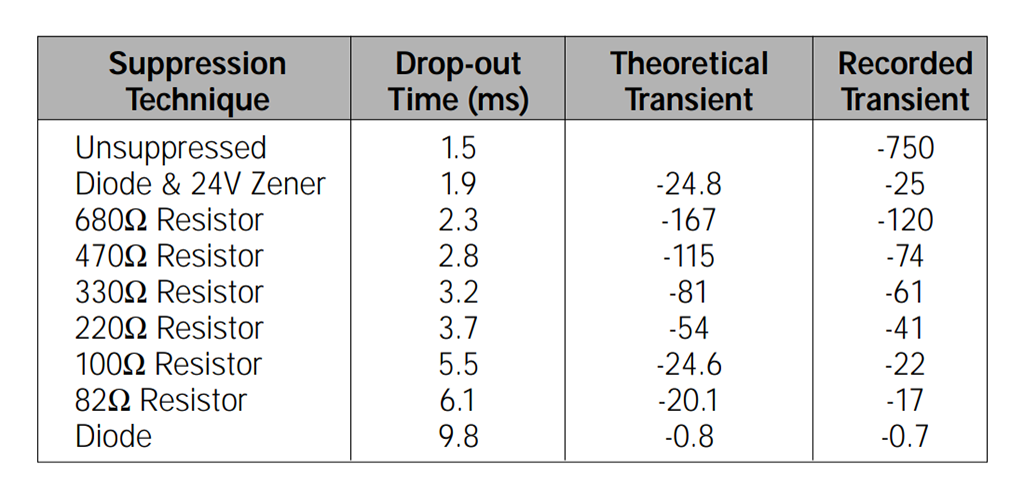
Figure 2. Impact of various coil suppression on the relay response time
Suggested Methods for Relay Coil Suppression
From the standpoint of physics, the suggested technique for relay coil transient suppression is to use a reversed-biased rectifier diode and series zener diode in parallel with the relay coil. This permits the relay to have optimum release dynamics and normally-open contact life. Such suppression may be incorporated easily into the circuitry for printed circuit board relays; however, when specifying suppression for a socket-mounted relay, this method may be less practical than using a resistor.
When the permissible transient voltage is large enough and power dissipation tolerable, the relay may be suppressed with a resistor. From the standpoint of a Failure Mode and Effects Analysis (FMEA), the resistor will provide less added risk of failure than the two diodes suggested above (provided that its value is high enough to avoid detrimental effects to the relay's release dynamics). It must be noted that the optimum resistor value for one type of relay will not necessarily be the right value for another type.
Now that we have provided suggested suppression techniques based on normally-open contact performance, we must add a qualifying comment concerning the normally-closed contacts. When the primary load is on the normally-closed contacts (and a small load or none on the normally-open), it may be desirable to use a rectifier diode alone as the relay suppression (or perhaps a rectifier diode and a lower value of series resistor). The retarded armature motion that adversely impacts normally-open contact performance will typically improve normally-closed contact performance. The improvement results from less contact bounce during closure of the normally-closed contacts. This results from the lower impact velocity created by the retarded armature motion and has been utilized in the past to improve normally-closed contact performance on certain relays.
The Need for Transient Suppression
This application note has been written in response to the numerous application problems resulting from improper relay coil suppression. The typical symptom is random "tack" welding of the normally-open contacts when switching an inductive load or a lamp load with high inrush current.
When an electromechanical relay is de-energized rapidly by a mechanical switch or semiconductor, the collapsing magnetic field produces a substantial voltage transient in its effort to disperse the stored energy and oppose the sudden change of current flow. A 12VDC relay, for example, may generate a voltage of 1,000 to 1,500 volts during turn-off. With the advent of modern electronic systems, this relatively large voltage transient has created EMI, semiconductor breakdown, and switch wear problems for the design engineer. It has thus become common practice to suppress relay coils with other components which limit the peak voltage to a much smaller level.
Types of Transient Suppression Utilized with Relays
The basic techniques for suppression of transient voltages from relay coils are shown in Figure
- As observed here, the suppression device may be in parallel with the relay coil or in parallel with the switch used to control the relay. It is normally preferred to have the suppression parallel to the coil since it can be located closer to the relay (except in the case of PC board applications where either may be used). When the suppression is in parallel with the relay coil, any of the following may be used.
A. A bilateral transient suppressor diode that is similar in V-I characteristics to two zener diodes connected cathode to cathode (or anode to anode).
B. A reverse-biased rectifier diode in series with a zener diode such that their anodes (or cathodes) are common and the rectifier prevents normal current flow.
C. A metal-oxide-varistor (MOV).
D. A reversed-biased rectifier diode in series with a resistor.
E. A resistor, when conditions permit its use, is often the most economical suppression.
F. A reversed-biased rectifier diode.
G. A resistor-capacitor "snubber". Generally the least economical solution and no longer considered a practical solution.
H. A bifilar wound coil with the second winding used as the suppression device. This is not very practical since it adds significant cost and size to the relay.
Suppression used in parallel with the switching element is likely to be either a zener diode or a resistor-capacitor "snubber." The comments associated with the "parallel to coil" application are also applicable to this circuit.
Suppressor Parallel to Switch
Figure 1. Schematic for Relay Coil Suppression: Suppressor Parallel to Coil, and Suppressor Parallel to Switch
Effects of Coil Suppression on Relay Dynamics and Life
Even though the use of coil suppression is becoming more significant, relays are normally designed without taking the dynamic impact of suppressors into account. The optimum switching life (for normally-open contacts) is therefore obtained with a totally unsuppressed relay and statements of rated electrical life are usually based on this premise. The successful "breaking" of a DC load requires that the relay contacts move to open with a reasonably high speed.
A typical relay will have an accelerating motion of its armature toward the unenergized rest position during drop-out. The velocity of the armature at the instant of contact opening will play a significant role in the relay's ability to avoid "tack welding" by providing adequate force to break any light welds made during the "make" of a high current resistive load (or one with a high in-rush current). It is the velocity of the armature that is most affected by coil suppression. If the suppressor provides a conducting path, thus allowing the stored energy in the relay's magnetic circuit to decay slowly, the armature motion will be retarded and the armature may even temporarily reverse direction. The reversing of direction and re-closing of the contacts (particularly when combined with inductive loads) often leads to random, intermittent "tack welding" of the contacts such that the relay may free itself if operated again or even jarred slightly.
Based upon the impact on armature motion and optimizing for normallyopen contacts, the best suppression method is to use a silicon transient suppressor diode. This suppressor will have the least effect on relay dropout dynamics since the relay transient will be allowed to go to a predetermined voltage level and then permit current to flow with a low impedance. This results in the stored energy being quickly dissipated by the suppressor. Transient suppressor diodes are available as bi-directional components and permit the relay to be non-polarized when installed internally. Note that if a uni-directional transient suppressor is used, a rectifier diode must be placed in series with it to block normal current flow and it has little advantage over the use of a zener diode. The transient suppressor should be selected such that its pulse energy rating exceeds any anticipated transient such as coil turn-off or motor "noise" found in the application.
A metal-oxide-varistor will provide results similar to those of transient suppressor diode, but will have a higher "on-state" impedance and will thus allow a higher voltage to be developed. As an example, a 33 volt transient suppressor diode may have a "clamping" voltage between 30 and 36 volts. In comparison, a 33 volt MOV will likely clamp the relay at 45 to 55 volts (based on a typical automotive relay with 130 mA coil current). When the additional voltage is no problem, an MOV may save cost over the transient suppressor diode and will also provide a non-polarized relay.
The use of a reversed-biased rectifier diode in series with a zener diode will provide the best solution when the relay can be polarized. This suppression is often recommended by Siemens Electromechanical Components (SEC) for use in automotive circuits. The impact on release dynamics is minimal and poses no loss of reliability. This is normally a low-cost method and the only design precaution is to select a zener with an appropriate breakdown voltage and impulse power specifications adequate for the relay in its application. In printed circuit board applications with transistors used as relay drivers, the zener diode can be placed "across" the transistor; that is, for a common emitter circuit, cathode connected to collector and anode connected to the emitter (the series rectifier diode is not used in this type of circuit).
A reversed-biased rectifier in series with a resistor may be used successfully with some relays when maximum load switching capacity is not required. Care must be taken to use a resistor large enough in value to quickly dissipate the relay's stored energy but yet stay within the desired peak voltage transient. The required resistor value may be approximated from the following equation:
R = Vpeak/Icoil
where:
R = resistor value in Ohms
Vpeak = peak transient voltage permitted
Icoil = steady-state relay coil current
The actual voltage peak observed will be lower than calculated by this formula due to energy losses in the resistor. When using this type of suppression it is best to consult the relay manufacturer for recommended values.
A resistor may also be used by itself as a transient suppressor when the additional power dissipation and resulting heat generated by the resistor can be tolerated. In most situations, this will provide the least expensive suppression method (assuming the resistor value can be properly sized to minimize its impact on relay performance). This method is normally recommended by SEC when the application requirements permit.
Many engineers use a rectifier diode alone to provide the transient suppression for relay coils. While this is cost effective and fully eliminates the transient voltage, its impact on relay performance can be devastating. Problems of unexplained, random "tack welding" frequently occur in these systems. In some applications, this problem is merely a minor nuisance or inconvenience and the controller or operator will cycle the relay until the proper response is obtained. In many applications; however, the first occurrence may cause a complete system failure or even present a hazardous situation. It is important that these systems be designed with another method of relay suppression.
To illustrate the impact of various coil suppression on the relay response time, consider the following data that was recorded using an automotive ISO type relay with a 55 ohm coil and with 13.5VDC applied to the coil.
Figure 2. Impact of various coil suppression on the relay response time
Suggested Methods for Relay Coil Suppression
From the standpoint of physics, the suggested technique for relay coil transient suppression is to use a reversed-biased rectifier diode and series zener diode in parallel with the relay coil. This permits the relay to have optimum release dynamics and normally-open contact life. Such suppression may be incorporated easily into the circuitry for printed circuit board relays; however, when specifying suppression for a socket-mounted relay, this method may be less practical than using a resistor.
When the permissible transient voltage is large enough and power dissipation tolerable, the relay may be suppressed with a resistor. From the standpoint of a Failure Mode and Effects Analysis (FMEA), the resistor will provide less added risk of failure than the two diodes suggested above (provided that its value is high enough to avoid detrimental effects to the relay's release dynamics). It must be noted that the optimum resistor value for one type of relay will not necessarily be the right value for another type.
Now that we have provided suggested suppression techniques based on normally-open contact performance, we must add a qualifying comment concerning the normally-closed contacts. When the primary load is on the normally-closed contacts (and a small load or none on the normally-open), it may be desirable to use a rectifier diode alone as the relay suppression (or perhaps a rectifier diode and a lower value of series resistor). The retarded armature motion that adversely impacts normally-open contact performance will typically improve normally-closed contact performance. The improvement results from less contact bounce during closure of the normally-closed contacts. This results from the lower impact velocity created by the retarded armature motion and has been utilized in the past to improve normally-closed contact performance on certain relays.