Maximize relay performance and reliability while providing protection to the control circuit from coil induced voltages
This application note deals with problems related to the methods used in deenergizing electromagnetic relay coils, particularly when a solid state switch is used, and how they affect relay life.
It is primarily concerned with the deenergization cycle of the relay, and discusses
- The armature and switching dynamics of the relay system upon coil deenergization.
- How coil induced voltages occur.
- Techniques for protecting the solid state switch.
- The adverse effect of a simple coil suppression diode on relay switching dynamics and contact life.
- The typical “sticking” between mating contacts and the reduced ability to break when using diode suppression.
- How the addition of a Zener diode to the ordinary diode can provide both voltage suppression and reliable switching performance.
Relay deenergization or “drop-out” in typical clapper-type relays normally develops as follows: As the coil supply is interrupted, the magnetic flux decays to the point where the decreasing magnetic holding force (trying to keep the armature seated) drops below the spring forces (trying to unseat it), and armature opening commences. As armature opening continues, spring forces reduces according to the armature position; the countering magnetic force, however, reduces both with armature position and with decay of coil current (both of which reduce coil magnetic flux).As the electrical current in a relay coil is interrupted, an induced voltage transient of the order of hundreds or even thousands of volts may be generated across that coil as its magnetic flux, which is linked by the coil turns, collapses. This induced voltage, plus the coil supply voltage, as shown in Fig. 1, appears across the coil interrupting switch in a simple series switching circuit.
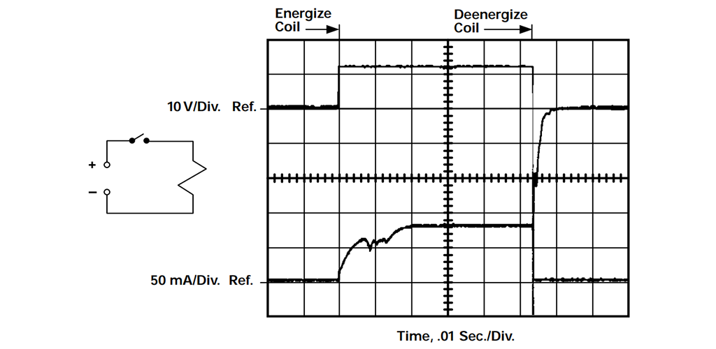
Figure 1. Operate & Release Dynamics Coil V & I, Typical DC Relay without Diode
In today’s logic control systems, a solid state switch is often used to operate a DC coil relay, and this switch is protected from coil deenergization induced voltages by various suppression techniques. These techniques are frequently effected by coil shunting means, designed to mitigate the suddenness of coil current interruption and resultant high rate of coil magnetic flux collapse.
One very common practice is to simply shunt the coil with a general purpose diode, placing the diode to block the source voltage and conduct with the reverse polarity of the coil induced voltage. This provides a path for the current flowing in the deenergized coil to be externally shunted back into the coil, limiting the magnitude of coil induced voltage to the forward drop of the diode, which the coil current, and resulting magnetic flux, slowly decay (see Fig. 2).
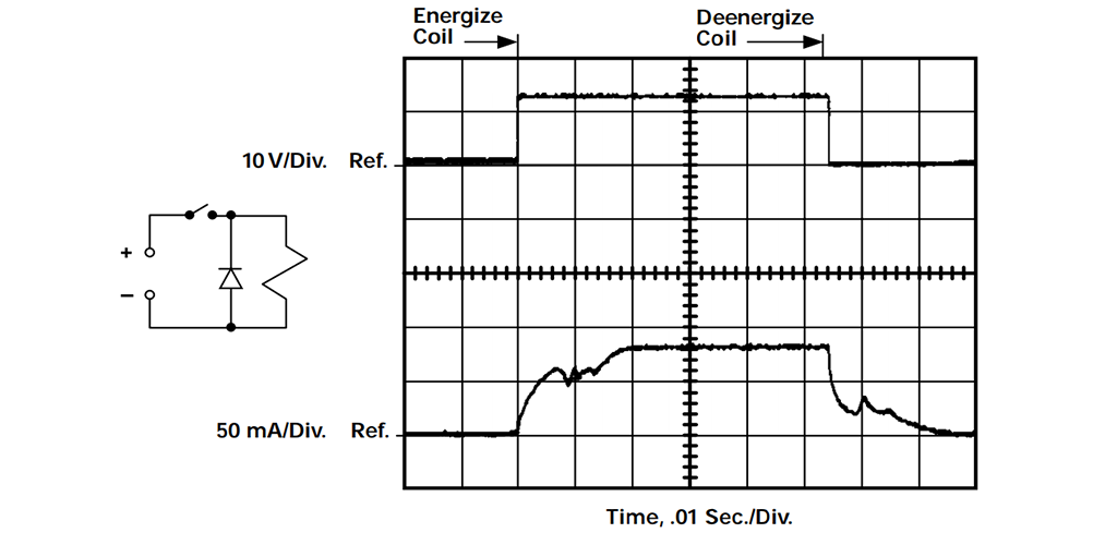
Figure 2. Operate & Release Dynamics Coil V & I, Typical DC Relay with Diode
This diode shunt provides maximum protection to the solid state switch, but may have very adverse effects on the switching capability of the relay. It is important to realize that the net force available to cause the armature to open is the difference between the magnetic restraining forces and the spring opening forces, that each of these is varying in a manner to cause the net force to vary both with time and armature position. It is this net force which gives rise to the armature system velocity and energy of momentum as it attempts to effect armature and contact spring transfer.
A slowly decaying magnetic flux (the slowest is experienced with a simple diode shunt across the coil) means the least net force integral available to accelerate the armature open. In fact, rapid loss of the opening forces supplied by stiff NO contact springs, coupled with slowly decaying magnetic forces, can actually cause a period of net force reversal where the armature velocity is slowed, stopped, or even momentarily reversed until the flux further decays, finally permitting available spring “return” forces to cause transfer to continue.
It is equally important to realize that when the contacts of a typical power relay make, connecting very fast rising (e.g., resistive) medium or high current loads to the voltage source, a minute molten interface occurs between the mating contacts, giving rise to a microweld or stick condition that must be separated at the next opening transfer.
The “stick” force is normally well within the ability of the net opening force, aided by the momentum of the moving armature, to break the stick and effect contact transfer. However, the loss or even reversal of armature velocity (under conditions of simple diode shunting as described above), and accompanying loss of armature momentum needed to help break the contact stick, can result in failure to break the stick, and a contact “weld” is experienced.
The more rapidly the coil current decays, the less the magnetic hold back, and thus the greater the armature momentum and contact stick “break-ability.”
Obviously, this is optimized when no suppression is used. However, near optimum decay rate can be obtained by using a Zener diode in series with a general purpose diode. When the coil source is interrupted, the coil current is shunted through this series arrangement, maintaining a voltage equal to the Zener voltage (plus forward diode drop) until the coil energy is dissipated. This is illustrated in Fig. 3.
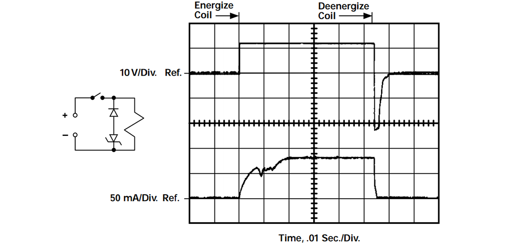
Figure 3. Operate & Release Dynamics Coil V & I, Typical DC Relay with Diode & 24V Zener
The Zener voltage value is chosen to limit the coil switch voltage to a level acceptable to the switch rating. This affords the best compromise both to coil switch protection and relay switching performance, and should be employed to assure maximum relay performance and reliability while providing protection to the control circuit from coil induced voltages.
It is normal industry practice to test relays and subsequently establish performance ratings without coil suppression. When application conditions require the suppression of coil induced voltages, it is recommended that the relay’s performance be evaluated with the suppression that will be used.
Maximize relay performance and reliability while providing protection to the control circuit from coil induced voltages
This application note deals with problems related to the methods used in deenergizing electromagnetic relay coils, particularly when a solid state switch is used, and how they affect relay life.
It is primarily concerned with the deenergization cycle of the relay, and discusses
- The armature and switching dynamics of the relay system upon coil deenergization.
- How coil induced voltages occur.
- Techniques for protecting the solid state switch.
- The adverse effect of a simple coil suppression diode on relay switching dynamics and contact life.
- The typical “sticking” between mating contacts and the reduced ability to break when using diode suppression.
- How the addition of a Zener diode to the ordinary diode can provide both voltage suppression and reliable switching performance.
Relay deenergization or “drop-out” in typical clapper-type relays normally develops as follows: As the coil supply is interrupted, the magnetic flux decays to the point where the decreasing magnetic holding force (trying to keep the armature seated) drops below the spring forces (trying to unseat it), and armature opening commences. As armature opening continues, spring forces reduces according to the armature position; the countering magnetic force, however, reduces both with armature position and with decay of coil current (both of which reduce coil magnetic flux).As the electrical current in a relay coil is interrupted, an induced voltage transient of the order of hundreds or even thousands of volts may be generated across that coil as its magnetic flux, which is linked by the coil turns, collapses. This induced voltage, plus the coil supply voltage, as shown in Fig. 1, appears across the coil interrupting switch in a simple series switching circuit.
Figure 1. Operate & Release Dynamics Coil V & I, Typical DC Relay without Diode
In today’s logic control systems, a solid state switch is often used to operate a DC coil relay, and this switch is protected from coil deenergization induced voltages by various suppression techniques. These techniques are frequently effected by coil shunting means, designed to mitigate the suddenness of coil current interruption and resultant high rate of coil magnetic flux collapse.
One very common practice is to simply shunt the coil with a general purpose diode, placing the diode to block the source voltage and conduct with the reverse polarity of the coil induced voltage. This provides a path for the current flowing in the deenergized coil to be externally shunted back into the coil, limiting the magnitude of coil induced voltage to the forward drop of the diode, which the coil current, and resulting magnetic flux, slowly decay (see Fig. 2).
Figure 2. Operate & Release Dynamics Coil V & I, Typical DC Relay with Diode
This diode shunt provides maximum protection to the solid state switch, but may have very adverse effects on the switching capability of the relay. It is important to realize that the net force available to cause the armature to open is the difference between the magnetic restraining forces and the spring opening forces, that each of these is varying in a manner to cause the net force to vary both with time and armature position. It is this net force which gives rise to the armature system velocity and energy of momentum as it attempts to effect armature and contact spring transfer.
A slowly decaying magnetic flux (the slowest is experienced with a simple diode shunt across the coil) means the least net force integral available to accelerate the armature open. In fact, rapid loss of the opening forces supplied by stiff NO contact springs, coupled with slowly decaying magnetic forces, can actually cause a period of net force reversal where the armature velocity is slowed, stopped, or even momentarily reversed until the flux further decays, finally permitting available spring “return” forces to cause transfer to continue.
It is equally important to realize that when the contacts of a typical power relay make, connecting very fast rising (e.g., resistive) medium or high current loads to the voltage source, a minute molten interface occurs between the mating contacts, giving rise to a microweld or stick condition that must be separated at the next opening transfer.
The “stick” force is normally well within the ability of the net opening force, aided by the momentum of the moving armature, to break the stick and effect contact transfer. However, the loss or even reversal of armature velocity (under conditions of simple diode shunting as described above), and accompanying loss of armature momentum needed to help break the contact stick, can result in failure to break the stick, and a contact “weld” is experienced.
The more rapidly the coil current decays, the less the magnetic hold back, and thus the greater the armature momentum and contact stick “break-ability.”
Obviously, this is optimized when no suppression is used. However, near optimum decay rate can be obtained by using a Zener diode in series with a general purpose diode. When the coil source is interrupted, the coil current is shunted through this series arrangement, maintaining a voltage equal to the Zener voltage (plus forward diode drop) until the coil energy is dissipated. This is illustrated in Fig. 3.
Figure 3. Operate & Release Dynamics Coil V & I, Typical DC Relay with Diode & 24V Zener
The Zener voltage value is chosen to limit the coil switch voltage to a level acceptable to the switch rating. This affords the best compromise both to coil switch protection and relay switching performance, and should be employed to assure maximum relay performance and reliability while providing protection to the control circuit from coil induced voltages.
It is normal industry practice to test relays and subsequently establish performance ratings without coil suppression. When application conditions require the suppression of coil induced voltages, it is recommended that the relay’s performance be evaluated with the suppression that will be used.