Linear Variable Differential Transformer
LVDTs provide reliable position measurement for applications in subsea, power generation, industrial automation, aerospace, test and measurement, and more.
What is an LVDT?
LVDT is an acronym for Linear Variable Differential Transformer. It is a common type of electromechanical transducer that can convert the rectilinear motion of an object to which it is coupled mechanically into a corresponding electrical signal. LVDT linear position sensors are readily available that can measure movements as small as a few millionths of an inch up to several inches, but are also capable of measuring positions up to ±30 inches (±0.762 meter). Figure 1 shows the components of a typical LVDT. The transformer's internal structure consists of a primary winding centered between a pair of identically wound secondary windings, symmetrically spaced about the primary. The coils are wound on a one-piece hollow form of thermally stable glass reinforced polymer, encapsulated against moisture, wrapped in a high permeability magnetic shield, and then secured in a cylindrical stainless steel housing. This coil assembly is usually the stationary element of the position sensor.
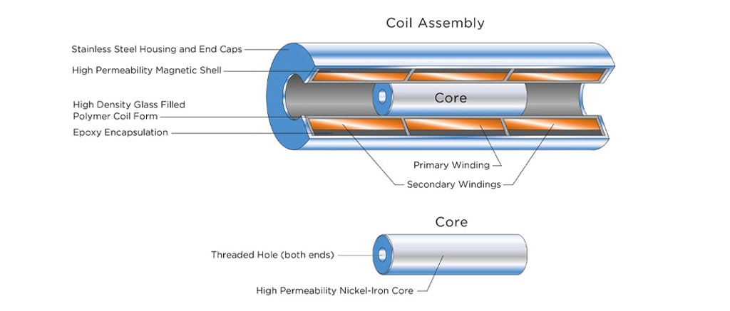
FIGURE 1: The primary winding is illustrated in the center of the LVDT. Two secondary coils are wound symmetrically on each side of the primary coil as shown for “short stroke” LVDTs or on top of the primary coil for “long stroke” LVDTs. The two secondary windings are typically connected in “series opposing” (Differential).
The moving element of an LVDT is a separate tubular armature of magnetically permeable material. This is called the core, which is free to move axially within the coil's hollow bore, and mechanically coupled to the object whose position is being measured. This bore is typically large enough to provide substantial radial clearance between the core and bore, with no physical contact between it and the coil. In operation, the LVDT's primary winding is energized by alternating current of appropriate amplitude and frequency, known as the primary excitation. The LVDT's electrical output signal is the differential AC voltage between the two secondary windings, which varies with the axial position of the core within the LVDT coil. Usually this AC output voltage is converted by suitable electronic circuitry to high level DC voltage or current that is more convenient to use.
How Does an LVDT Work?
Figure 2 illustrates what happens when the LVDT's core is in different axial positions. The LVDT's primary winding, P, is energized by a constant amplitude AC source. The magnetic flux thus developed is coupled by the core to the adjacent secondary windings, S1 and S2. If the core is located midway between S1 and S2, equal flux is coupled to each secondary so the voltages, E1 and E2, induced in windings S1 and S2 respectively, are equal. At this reference midway core position, known as the null point, the differential voltage output, (E1 - E2), is essentially zero. As shown in Figure 2, if the core is moved closer to S1 than to S2, more flux is coupled to S1 and less to S2, so the induced voltage E1 is increased while E2 is decreased, resulting in the differential voltage (E1 - E2). Conversely, if the core is moved closer to S2, more flux is coupled to S2 and less to S1, so E2 is increased as E1 is decreased, resulting in the differential voltage (E2 - E1).
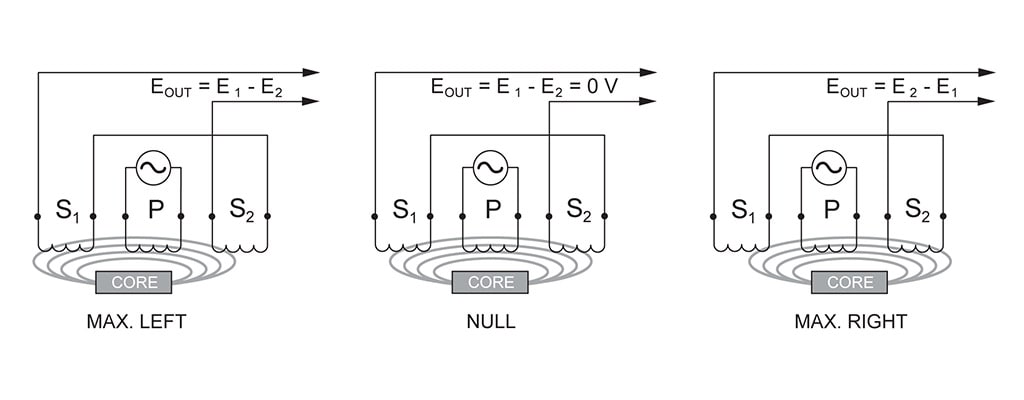
FIGURE 2: Illustrates what happens when the LVDT's core is in different axial positions.

Figure 3A shows how the magnitude of the differential output voltage, EOUT, varies with core position. The value of EOUT at maximum core displacement from null depends upon the amplitude of the primary excitation voltage and the sensitivity factor of the particular LVDT, but is typically several volts RMS. The phase angle of this AC output voltage, EOUT, referenced to the primary excitation voltage, stays constant until the center of the core passes the null point, where the phase angle changes abruptly by 180 degrees, as shown graphically in Figure 3B. This 180 degree phase shift can be used to determine the direction of the core from the null point by means of appropriate circuitry. This is shown in Figure 3C, where the polarity of the output signal represents the core's positional relationship to the null point. The figure shows also that the output of an LVDT is very linear over its specified range of core motion, but that the sensor can be used over an extended range with some reduction in output linearity.
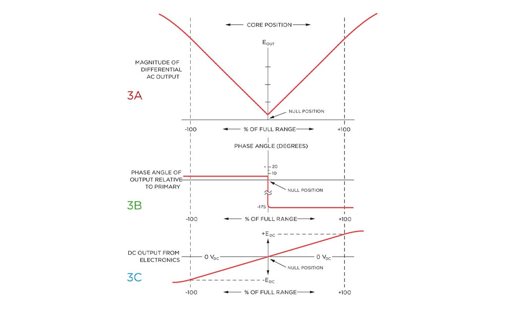
FIGURE 3: The output characteristics of an LVDT vary with different positions of the core. Full range output is a large signal, typically a volt or more, and often requires no amplification. Note that an LVDT continues to operate beyond 100% of full range, but with degraded linearity.
LVDT Support Electronics
Although an LVDT is an electrical transformer, it requires AC power of an amplitude and frequency quite different from ordinary power lines to operate properly (typically 3 Vrms at 3 kHz). Supplying this excitation power for an LVDT is one of several functions of LVDT support electronics, which is also sometimes known as LVDT signal conditioning equipment. Other functions include converting the LVDT's low level AC voltage output into high level DC signals that are more convenient to use, decoding directional information from the 180 degree output phase shift as an LVDT's core moves through the null point, and providing an electrically adjustable output zero level. A variety of LVDT signal conditioning electronics is available, including chip-level and board-level products for OEM applications as well as modules and complete laboratory instruments for users.

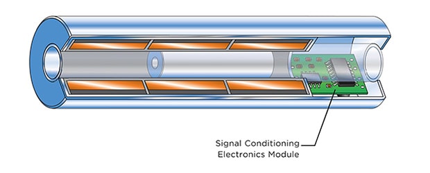
The support electronics can also be self-contained, as in the DC-LVDT shown in Figure 4. These easy-to-use position transducers offer practically all of the LVDT's benefits with the simplicity of DC-in, DC-out operation. Of course, LVDTs with integral electronics may not be suitable for some applications, or might not be packaged appropriately for some installation environments.
Why Use an LVDT?
Friction-Free Operation
One of the most important features of an LVDT is its friction-free operation. In normal use, there is no mechanical contact between the LVDT's core and coil assembly, so there is no rubbing, dragging, or other source of friction. This feature is particularly useful in materials testing, vibration displacement measurements, and high resolution dimensional gaging systems.
Infinite Resolution
Since an LVDT operates on electromagnetic coupling principles in a friction-free structure, it can measure infinitesimally small changes in core position. This infinite resolution capability is limited only by the noise in an LVDT signal conditioner and the output display's resolution. These same factors also give an LVDT its outstanding repeatability.
Unlimited Mechanical Life
Because there is normally no contact between the LVDT's core and coil structure, no parts can rub together or wear out. This means that an LVDT features unlimited mechanical life. This factor is especially important in high reliability applications such as aircraft, satellites and space vehicles, and nuclear installations. It is also highly desirable in many industrial process control and factory automation systems.
Overtravel Damage Resistant
The internal bore of most LVDTs is open at both ends. In the event of unanticipated overtravel, the core is able to pass completely through the sensor coil assembly without causing damage. This invulnerability to position input overload makes an LVDT a suitable sensor for applications like extensometers that are attached to tensile test samples in destructive materials testing apparatus.
Single Axis Sensitivity
An LVDT responds to motion of the core along the coil's axis, but is generally insensitive to cross-axis motion of the core or to its radial position. Thus, an LVDT can usually function without adverse effect in applications involving misaligned or floating moving members, and in cases where the core does not travel in a precisely straight line.
Separable Coil And Core
Because the only interaction between an LVDT's core and coil is magnetic coupling, the coil assembly can be isolated from the core by inserting a non-magnetic tube between the core and the bore. By doing so, a pressurized fluid can be contained within the tube, in which the core is free to move, while the coil assembly is unpressurized. This feature is often utilized in LVDTs used for spool position feedback in hydraulic proportional and/or servo valves.
Environmentally Robust
The materials and construction techniques used in assembling an LVDT result in a rugged, durable sensor that is robust to a variety of environmental conditions. Bonding of the windings is followed by epoxy encapsulation into the case, resulting in superior moisture and humidity resistance, as well as the capability to take substantial shock loads and high vibration levels in all axes. And the internal high-permeability magnetic shield minimizes the effects of external AC fields. Both the case and core are made of corrosion resistant metals, with the case also acting as a supplemental magnetic shield. And for those applications where the sensor must withstand exposure to flammable or corrosive vapors and liquids, or operate in pressurized fluid, the case and coil assembly can be hermetically sealed using a variety of welding processes. Ordinary LVDTs can operate over a very wide temperature range, but, if required, they can be produced to operate down to cryogenic temperatures, or, using special materials, operate at the elevated temperatures and radiation levels found in many nuclear reactors.
Null Point Repeatibility
The location of an LVDT's intrinsic null point is extremely stable and repeatable, even over its very wide operating temperature range. This makes an LVDT perform well as a null position sensor in closed-loop control systems and high-performance servo balance instruments.
Fast Dynamic Response
The absence of friction during ordinary operation permits an LVDT to respond very fast to changes in core position. The dynamic response of an LVDT sensor itself is limited only by the inertial effects of the core's slight mass. More often, the response of an LVDT sensing system is determined by characteristics of the signal conditioner.
Absolute Output
An LVDT is an absolute output device, as opposed to an incremental output device. This means that in the event of loss of power, the position data being sent from the LVDT will not be lost. When the measuring system is restarted, the LVDT's output value will be the same as it was before the power failure occurred.