Application Note
Digital Thermopiles
Learn more about the functionality and usage of digital thermopile sensors for contactless temperature measurement.
Overview
The main function of a thermopile sensor is to transfer the heat radiation emitted from the objects into an output signal. This sensor technology is used in various applications including: appliances (microwave ovens, clothes dryer, automatic cooking), medical devices (ear and forehead thermometers), automotive (car climate control, seat occupancy, blind spot alert, and black ice warning), consumer products (printers, copiers, mobile phones) and many industrial applications like paper web, plastic parts etc.
Infrared Temperature Measurement
Any object emits infrared radiation. The radiation power is increasing with growing surface temperatures. Based on this relation, thermopiles measure the emitted power and determine the object’s temperature precisely. Thermopile infrared sensors are based on two physical effects: • Black body radiation: Any object with a temperature above 0 K emits electromagnetic radiation according Planck’s law. The integral over Planck’s curve is called the Stefan-Boltzmann-Law which gives the total emitted power: P = A * e * s*T4 P=emitted power, A=surface area, e=emissivity of surface, s=Stefan-Boltzmann-Constant=5.67·10-8W/(m2·K4), T=absolute temperature (in K) • For surface temperatures <700°C this infrared radiation only. If the surface temperature exceeds 700°C an increasing part of the emitted radiation is visible light, e.g. glowing steel, incandescent lamp etc. • Seebeck effect: Exposing a pair of contacts of dissimilar conductors to a temperature difference results in a voltage difference.
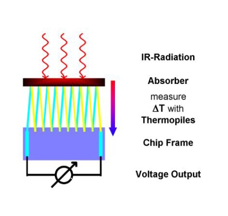
Thermopile Sensor Function
The thermopile infrared sensor consists of an absorber, which is thermally isolated from a frame and in series connected thermocouples. When the absorber is pointed towards an object with a temperature different from the absorber, then the power emitted by object and absorber differs as well. There is a netto radiative heat flow to/from the absorber which is heating/cooling the absorber. This resulting temperature difference between absorber and frame is converted by the thermopile (acc. Definition 1) into a voltage. When also the temperature of the frame is measured, using e.g. a NTC thermistor, the objects temperature can be calculated using the Stefan-Boltzmann-Law.
Transport Recommendations
• Avoid touching of silicon window • Avoid contamination of silicon window • Avoid damage of silicon window (scratches, etc.) • Avoid pin deformation • Avoid compression of component housing
Cleaning Recommendations
• Isopropanol (other names: Iso-Propyl-Acohol (IPA), 2-Propanol), use medical grade, pro analysis grade or purer • Scratch and lint free cleaning tissue (e.g. Bemcot M-3II) Using the wet tissue: Clean from the center of the window or lens to the outside. Take care that you also clean the tiny step between optics and metal case of the thermopile properly • Check for stains after wet cleaning, if necessary repeat the wet cleaning • Check for lints after wet cleaning, if necessary wipe of lints with a dry tissue • Please Note: Some Q-tips have the cotton attached to the stick with glue. In some cases this glue is dissolved by the isopropanol and leaves a deposit on the optics. Due the infrared absorption of this deposit the calibration may be compromised.
Solder Recommendations
Process |
Temperature |
Max. Duration / s |
Comment |
Wave Soldering 1 |
260°C ±5°C |
10 |
AOI recommended |
Hand Soldering 1 |
375°C ±10°C |
4 |
Control for flux residue and other contamination on the surface of the PCBA recommended |
Reflow Soldering |
Not Recommended |
||
Direct Sunlight
Sun light radiation which is transmitted through a glass window may influence the measurement accuracy. To avoid this, the thermopile sensor is equipped with a long wavelength filter. Due to filter characteristics a small portion of radiation will be added to the radiation of the object. In case of direct sunlight exposure this error can be up to +0.2°C.
Touching the Sensors Cap
User should avoid touching the sensors cap. There will still be a measurement deviation after changing the sensors temperature rapidly
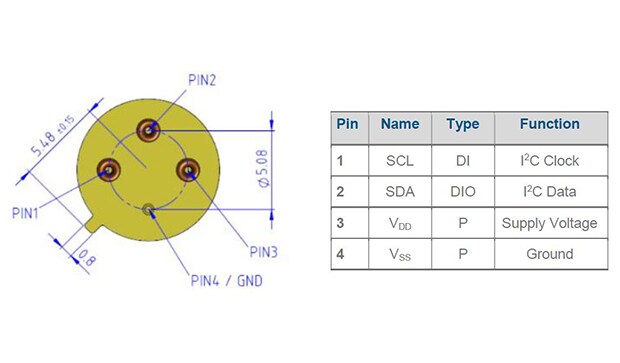
Setting up Connections
Below is the example as to how one needs to set up connections
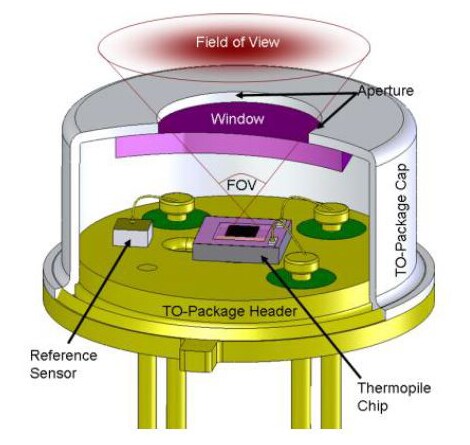
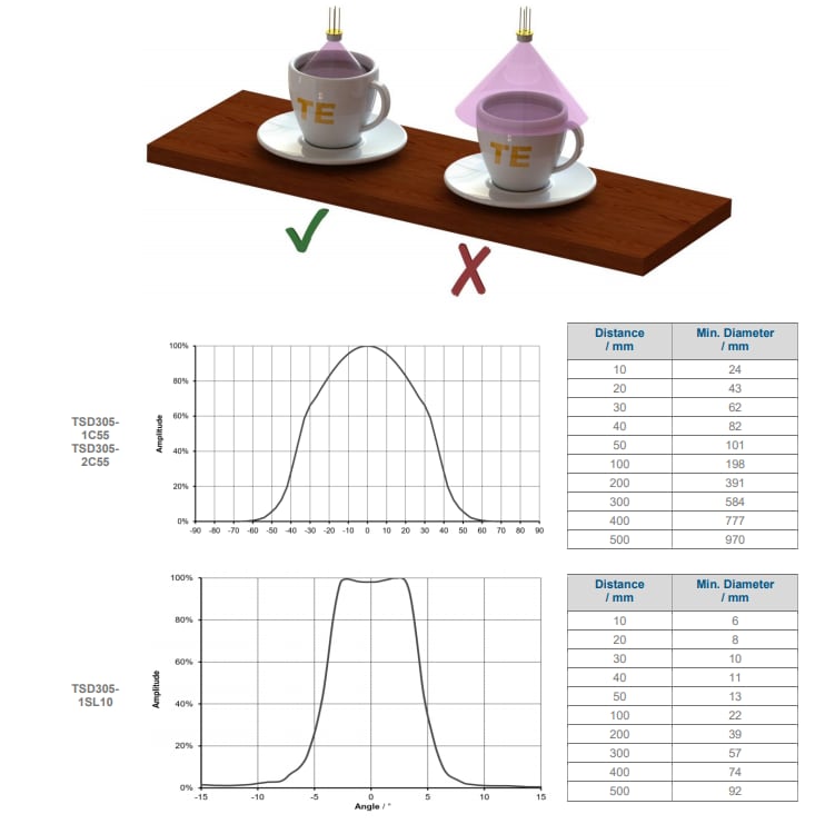
Field of View
The thermopile’s field of view must be directed to the object surface of interest. The distance to the surface or the surface diameter must be adjusted to ensure that the complete sensors field of view is covered by the object, see example on the left in the picture below.
Emissivity
Every object is transmitting infrared energy in dependence to its temperature. The emissivity is the ratio of the radiated power by an object to the radiation of an ideal black body. Common materials like liquids, clothes, human skin, foods have emissivity factors >0.90 and therefore they can be measured very accurately without adopting the sensors specification.
To compensate the measurement for an object with significant low emissivity, ADCobj needs to be adjusted.
Name |
Description |
Format |
Range |
|
Min |
Max |
|||
ADCobj |
ADC Object Temperature Shifted by 223 (0 is represented by 8,388,608) |
INT24 |
0 |
16,777,216 |