Industries
Linear Variable Differential Transformer (LVDT) Basics
LVDTs provide reliable position measurement for applications in subsea, power generation, industrial automation, aerospace, test and measurement, and more.
The Linear Variable Differential Transformer, also known as an LVDT, is a common type of electromechanical transducer that can convert the rectilinear motion of an object to which it is coupled mechanically into a corresponding electrical signal. LVDT linear position sensors are readily available that can measure movements as small as a few millionths of an inch up to several inches, but are also capable of measuring positions up to ±30 inches (±0.762 meter).
How Does an LVDT Work?
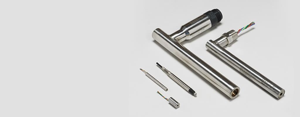
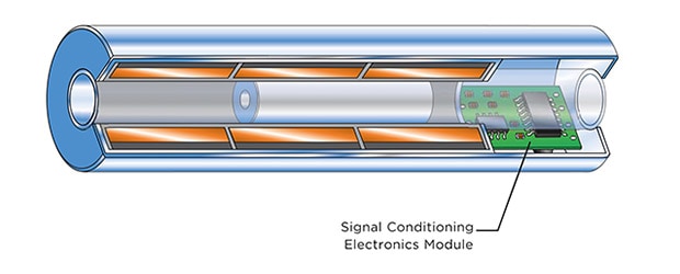
The internal structure of an LVDT consists of a primary winding centered between a pair of identical secondary windings, symmetrically spaced about the primary winding. The coils are wound on a one-piece hollow form of thermally stable glass reinforced polymer, encapsulated against moisture, wrapped in a high permeability magnetic shield, and then secured in a cylindrical stainless steel housing. This coil assembly is usually the stationary element of the position sensor.
The moving element of an LVDT is a separate tubular armature of magnetically permeable material. This is called the core, which is free to move axially within the coil's hollow bore, and mechanically coupled to the object whose position is being measured. This bore is typically large enough to provide substantial radial clearance between the core and bore, with no physical contact between it and the coil. In operation, the LVDT's primary winding is energized by alternating current of appropriate amplitude and frequency, known as the primary excitation. The LVDT's electrical output signal is the differential AC voltage between the two secondary windings, which varies with the axial position of the core within the LVDT coil. Usually this AC output voltage is converted by suitable electronic circuitry to high level DC voltage or current that is more convenient to use.
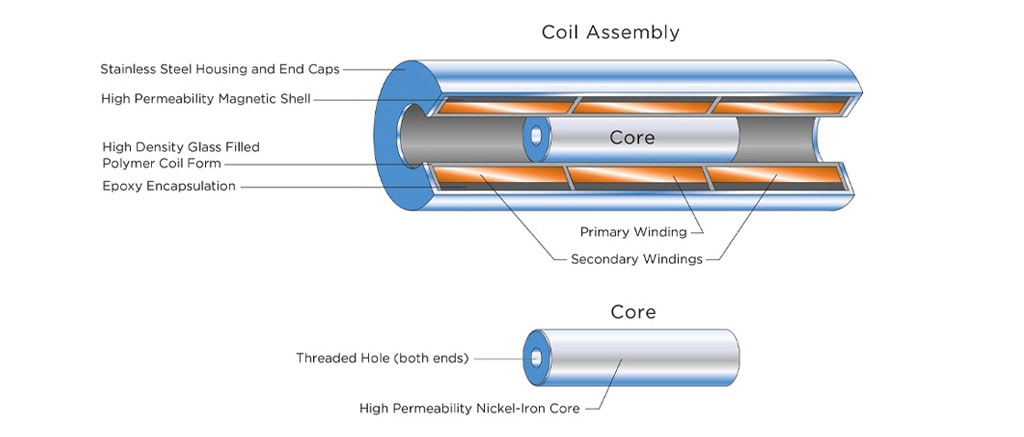
Components of a typical LVDT (Figure 1): The primary winding is illustrated in the center of the LVDT. Two secondary coils are wound symmetrically on each side of the primary coil as shown for “short stroke” LVDTs or on top of the primary coil for “long stroke” LVDTs. The two secondary windings are typically connected in “series opposing” (Differential).

Axial Positions
The LVDT's primary winding, P, is energized by a constant amplitude AC source. The magnetic flux thus developed is coupled by the core to the adjacent secondary windings, S1 and S2. If the core is located midway between S1 and S2, equal flux is coupled to each secondary so the voltages, E1 and E2, induced in windings S1 and S2 respectively, are equal. At this reference midway core position, known as the null point, the differential voltage output, (E1 - E2), is essentially zero.
As shown in Figure 2, if the core is moved closer to S1 than to S2, more flux is coupled to S1 and less to S2, so the induced voltage E1 is increased while E2 is decreased, resulting in the differential voltage (E1 - E2). Conversely, if the core is moved closer to S2, more flux is coupled to S2 and less to S1, so E2 is increased as E1 is decreased, resulting in the differential voltage (E2 - E1).
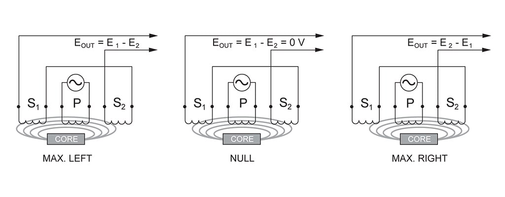
Figure 2: Illustrates what happens when the LVDT's core is in different axial positions.
Core Types
Both free-core and guided-core LVDT linear position sensors provide the benefit of infinite resolution, with each type offering models that can operate in harsh environments. While free-core LVDTs are generally less expensive and available in many ranges, they are more difficult to install than guided-core sensors. Available in spring and air-loaded cores, guided-core LVDTs are simpler to install but more expensive and not available in as many ranges. In addition to these differences, some applications are just better suited for a free-core LVDT, while others can benefit from a guided-core LVDT.
Free-Core LVDTs
The moving element of a free-core LVDT is a separate tubular armature of magnetically permeable material called the core, which is free to move axially within the coil's hollow bore, and mechanically coupled to the object whose position is being measured. This bore is typically large enough to provide substantial radial clearance between the core and bore, with no physical contact between it and the coil for friction-less measurement and virtually infinite mechanical life.
Free-core LVDTs are very versatile, non-contacting and robust, offering long-term reliability in harsh or hostile environments when constructed with the right materials. Frictionless operation translates into higher repeatability and resolution. Based on these properties, LVDTs are typically used in systems where cost of ownership, safety and high reliability are priorities, such as aircraft wing-flap indication, subsea applications, high-temperature steam valves, and power plant installations.
Other suitable applications for free-core LVDTs include:
- Where the measured object is mechanically coupled to the reference surface or object (valves, hydraulic cylinders, actuators, strain testing machines)
- Measuring ranges above 4.00” frequency response >10 Hz (vibration measurements)
- Critical measurement of delicate materials or highly elastic materials that allow the measured object to move with little to no mechanical resistance.
Spring Loaded LVDTs
Commonly referred to as dimensional gauging probes, spring-loaded LVDTs incorporate a non-contacting, inductive position sensor, either an LVDT or half bridge, that includes a spring-loaded movable armature coupled to a shaft supported in a high-precision linear bearing. Most gauging probes have a maximum gauging range of ±0.50 mm to ±50.0 mm (±0.020 in. to ±2.00 in.), with resolutions of fractions of microns. When electronics are built into a spring-loaded assembly, there is no need for external electronics, making the mechanical setup of the sensor into automated machinery less complicated and more cost effective.
Electronic gauging probes are commonly used in the dimensional gauging of manufactured parts, serving as important components of quality assurance systems. Suitable applications are where the measured object is not mechanically coupled to the reference:
- Gauging in heavy industrial: hermetically-sealed gauging probes can solve many of the problems associated with dimensional gauging in harsh environments
- High precision gauging: High precision gauging probes utilize a linear ball bearing assembly precisely fitted to a hardened and ground, non-rotating probe shaft to minimize radial play and the effects of side loading. This results in the probes' exceptional repeatability of 0.000006 inch (0.15 μm)
- Assembly line quality measurements: Air extend/spring-retract gauging probes are recommended for these applications as they extend to make measurements and then retract so the probe is not damaged as product moves down the line
- Flatness measurements on plates
- Potential cross-axial movement of the measured object: For example, making a roundness measurement on a rotating part
Output Signals
An AC-operated LVDT linear position sensor does not contain any internal electronics and requires an external oscillator, carrier amplifier, or demodulators and filters to operate. A DC-operated LVDT linear position sensor is comprised of an AC-operated LVDT and a carrier generator/signal conditioning module. It maintains all the desirable characteristics of the AC-LVDT, but has the simplicity of DC operation. Applications often dictate the choice of an AC or DC LVDT output signal.
AC-Operated LVDT Sensors
- A basic AC LVDT consists of a primary coil and two secondary coils
- The ferromagnetic core inside the coil assembly provides a path for the magnetic flux linking the coils
- When the primary coil is energized with an AC voltage (typically 3-7 Vrms at 2.5 kHz), the voltage is inductively coupled by the core to the two secondaries
- The coil assembly is held stationary while the core is attached by a connecting rod to the moving object
- Using electronics, the exact position of the core inside the coil assembly can be determined
DC-Operated LVDT Sensors
Integral signal conditioning circuit
- An internal oscillator excites the coils with the necessary AC signal
- The DC LVDT has a small signal conditioning circuit packaged inside the sensor body
- The synchronous demodulator circuit reads the output from the secondary coils, then rectifies and amplifies it to a scaled DC signal proportional to the full range of the LVDT core position
Output Voltage
Differential Output Voltage
The magnitude of the differential output voltage, EOUT, varies with core position. The value of EOUT at maximum core displacement from null depends upon the amplitude of the primary excitation voltage and the sensitivity factor of the particular LVDT, but is typically several volts RMS.
The phase angle of this AC output voltage, EOUT, referenced to the primary excitation voltage, stays constant until the center of the core passes the null point, where the phase angle changes abruptly by 180 degrees, as shown graphically in Figure 3B.
This 180 degree phase shift can be used to determine the direction of the core from the null point by means of appropriate circuitry. This is shown in Figure 3C, where the polarity of the output signal represents the core's positional relationship to the null point. The figure shows also that the output of an LVDT is very linear over its specified range of core motion, but that the sensor can be used over an extended range with some reduction in output linearity.
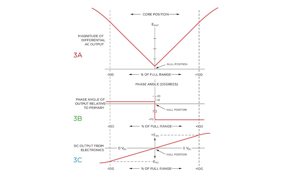
Figure 3: The output characteristics of an LVDT vary with different positions of the core. Full range output is a large signal, typically a volt or more, and often requires no amplification. Note that an LVDT continues to operate beyond 100% of full range, but with degraded linearity.
Signal Conditioners
Although an LVDT is an electrical transformer, it requires AC power of an amplitude and frequency quite different from ordinary power lines to operate properly (typically 3 Vrms at 3 kHz). Supplying this excitation power for an LVDT is one of several functions of LVDT support electronics, which is also sometimes known as LVDT signal conditioning equipment. Other functions include converting the LVDT's low level AC voltage output into high level DC signals that are more convenient to use, decoding directional information from the 180 degree output phase shift as an LVDT's core moves through the null point, and providing an electrically adjustable output zero level. A variety of LVDT signal conditioning electronics is available, including chip-level and board-level products for OEM applications as well as modules and complete laboratory instruments for users.
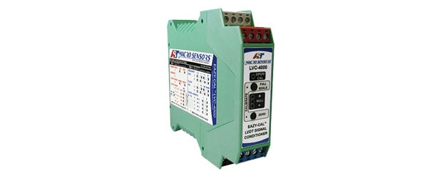
The support electronics can also be self-contained, as in the DC-LVDT shown in Figure 4. These easy-to-use position transducers offer practically all of the LVDT's benefits with the simplicity of DC-in, DC-out operation. Of course, LVDTs with integral electronics may not be suitable for some applications, or might not be packaged appropriately for some installation environments.
Electrical Connections
Connectors and lead wires provide the electrical connection between the coils of an LVDT position sensor and signal conditioning electronics. Below are some helpful tips to guide you in deciding whether to specify a connector or lead wires for your next sensor.
Wire Leads
LVDT sensors are most commonly specified with lead wires as they are generally less expensive than connectors and easy to use, providing a simple connection to signal conditioning electronics for bench-top testing. In some cases, lead wires can offer expanded operating ranges in both temperature and pressure. For example, lead wires are the preferred electrical connection for sensors used in high pressure, in-cylinder hydraulic applications or when operating temperatures exceed 400°F.
Lead wire sensitivity, however, is a potential drawback to its use as the wire can break if not handled carefully during installation. Long runs of leads also can be cumbersome and complicated to install. In addition, lead wires are susceptible to picking up noise that can affect interpretation of signals by the conditioning equipment, ultimately reducing the accuracy of the sensor output.
Connectors
Independent of wiring, sensors with connectors are easier to install and uninstall. When reinstalling a sensor, connectors can simply be unplugged or plugged into while lead wires must be broken and often repaired. Connectors also can be specified with shielded cable assemblies to create longer distances between the LVDT linear position sensor and electronics, which is especially important when sensors must perform in harsh environments, as cabling has lower resistance and shielding that protects against interference from outside sources.
If wires are broken or pulled on the cable assembly, only the cable assembly has to be replaced as the LVDT sensor will otherwise remain in working order. Breaking or stripping a lead wire by pulling on it too hard makes the sensor non-repairable, requiring the purchase of a replacement sensor. Through the use of connectors, LVDT sensors can be hermetically sealed, offering ingress protection ratings to IP-68. Connectors can be bulky and difficult to fit into tight spaces or on LVDTs with small package size requirements.
When determining the best electrical connection for an LVDT sensor, gather facts on the environment where the sensor will be placed as different elements can effect performance.
- Temperatures in excess of 400°F: leads may be better suited high pressure: in conductive fluids like water: require a connector; in fluids that are not electrically conductive like hydraulic fluid, leads can be used
- Dust and humidity: glass-sealed connectors offer better environmental protection against heavy dust, humidity and submersion
- Vibrations: If the sensor will be exposed to constant shock and vibration over a long period of time, leads or a screw-on connector offer the best options
Recommended applications when choosing between wire leads and connectors. Note that application requirements should always be checked along with LVDT performance specifications.
| Applications | Lead Wire | Connector |
|---|---|---|
| Simple Bench-Top Setup | X | |
| Frequent In-Field Replacement | X | |
| Clean/Dry Environments | X | |
| Heavy Dust/Dirt/Humidity | X | |
| Light Dust/Dirt | X | |
| High Pressure Hydraulic Oil | X | |
| Freshwater/Seawater Submersion | X |
Environmental Considerations
If heavy dust, dirt, humidity, or jetting are present, or if the sensor will be installed outdoors, a hermetically-sealed LVDT is recommended to confirm outside media does not enter the windings that can shorten sensor life or reliability. In a more benign or indoor laboratory environment, a standard non-hermetically sealed transducer will get the job done with a lower up-front cost.
For in-cylinder applications with hydraulic fluid, a vented LVDT will perform well. Vented versions of LVDT linear position sensors can withstand a combination of high pressure, temperatures, shock, and vibration as the coil assembly of the sensor is vented to equalize pressure inside and outside the LVDT linear position sensor.
Special configurations of LVDTs also offer mild resistance to radiation and operation when submerged underwater or in high pressures or atmospheric conditions. For example, certain types of stainless steel cannot be used in LVDT construction when sensors come in direct contact with seawater. To survive in subsea environments, the LVDT casing should be constructed of special alloys that extend chemical resistance to seawater. These superalloys enhance the already high-reliability of the LVDT assembly, confirming that it can meet extended service life requirements, even if the device is fully exposed to seawater at depths up to 15,000 feet with external pressures of approximately 7500 psi.
Alloy 400 is a special nickel-based alloy that provides excellent resistance against pitting and attack by micro-organisms, enabling sensors to perform in shallow and warm waters with high levels of oxygen without the threat of sea life forming on it. In subsea applications with depths of 7500 ft. and external pressures surpassing 3500 psi, Inconel, Titanium, and Hastelloy offer excellent protection against corrosion due to higher content of nickel, chromium, and molybdeumn.
When designed with Alloy 625 or 718 for pressure and corrosion resistance, an LVDT assembly can provide reliable operations for many years, even if the device is fully exposed to seawater. While these alloys cost more than stainless steel, they offer immunity against localized corrosion as well as oxidizing and reducing elements. Exotic alloys such as cobalt, nickel, and chromium with mineral insulation can deliver even higher performance from LVDTs where comparable technologies will not survive.
IP Ratings
LVDT linear position sensors are typically rated between IP-61 – IP-69. While dust tight in virtually all configurations, LVDT sensors have different levels of water ingress protection based on construction. For example, some LVDT sensors are built with limited coil protection, while others are protected with varnish or epoxies. Hermetically-sealed LVDTs are welded closed to prevent intrusion of the sensor. Each type of LVDT construction bears a different IP rating and may vary by manufacturer.
Non-Hermetically Sealed LVDTs
IP-61 Rating
The external sealing of non-hermetically sealed LVDT linear position sensor meets IEC standard IP-61. As these sensors are protected from dust ingress and condensation, they are suitable for the following applications:
- Dry environments with limited dust/dirt exposure
- Laboratory testing
- Indoor applications
- Precision gauging
- Dial indicator replacement
- Robot actuator position feedback
When coils are completely encapsulated in epoxy, the non-hermetically sealed LVDT position sensors increase their rating to IP-64, making them suitable for use in environments where heavy humidity may occur.
Hermetically Sealed LVDTs
IP-68 Rating
Constructed entirely of stainless steel, hermetically-sealed LVDTs incorporate coil windings that are sealed against hostile environments to IEC standard IP-68. In addition to being protected from total dust ingress, these sensors are rated for long-term water immersion up to a specified pressure without water ingress.
Recommended applications for IP-68 rated LVDTs include:
- Outdoor structural monitoring
- Applications with dust, dirt, grease, humidity
- Heavy industrial
- Valve position
All sensors rated by manufacturers to achieve IP-68 may not be the same but must exceed IP-67 ratings. IP-68 sensors are sealed via welding, with all wetted parts constructed of metal with the exception of the connector. The sensors themselves can be submerged in water or other fluids up to 1,000 psi when not operational. However, they cannot operate while submerged because water could intrude into the mating plug and cause a short.
Submersible LVDTs
IP-68 Rating
Submersible LVDTs are rated at IP-68 with appropriate Seacon-Branter mating connector. The connector and mating plug are rated for pressures up to 5,000 psi or higher. Typically, these units are designed with a 20-year life for use in critical applications where access to the unit for replacement or repair is very costly.
Recommended applications:
- Seawater or fresh water
- Dam/bridge structural monitoring
- Choke/Christmas tree valve position monitoring
- Subsea extensometers
- Mooring cables
- ROV actuator/latch position feedback