HOW TO ADDRESS WIRELESS CONNECTIVITY IN IOT DEVICES
When it comes to engineering smart IoT devices, proper antenna selection and positioning are critical considerations that need to be accounted for early in the design phase.
Customer: Exelonix
Key Notes
Customer
Exelonix (www.exelonix.com)
Country
Germany
Industry
Smart IoT devices (fleet management)
Challenges
Weak transmission and battery performance issues duringfield testing the first design iteration of a fleet tracking device.
Solutions
- Collaboration with TE
- Custom antenna that incorporates cellular, Bluetooth and GNSS antennas with maximum ground plane distance.
Customer Advantage
- Final antenna design achieved an efficiency of >30%, which surpassed the certification limit of >20%
- GNSS performance increased up to 99.9%
- Number of messages to be transmitted with the battery capacity increased by a factor of nearly 10

Understanding the effects of making early design considerations for antenna selection and integration on IoT device performance.
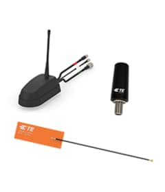
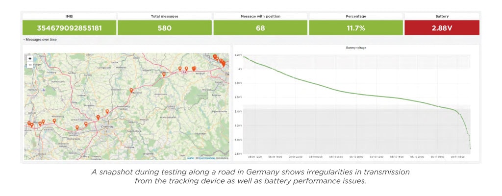
When it comes to engineering smart Internet of Things (IoT) devices and delivering a compact product with optimum signal performance and extended battery life, proper antenna selection and positioning are critical considerations that need to be accounted for early in the design phase. Exelonix, a German company that provides wireless IoT devices and software services to B2B customers, was in its first design iteration of a new fleet tracking device, but quickly realized during field tests that the radio frequency (RF) components were not functioning properly. The initial design incorporated a low-cost, off-the-shelf antenna that indicated great performance on data sheets and application notes. However, when the device was tested in the field, the results showed weak transmission performance with an efficiency of only 7% on cellular and a low-performing global navigation satellite system (GNSS) antenna. It was also clear that compensating for these low efficiencies with a low noise amplifier (LNA) or software workaround would not address the physics limitations of the initial antenna selection and placement. That’s when Exelonix engaged TE Connectivity (TE) to assess the root cause and develop a custom antenna solution.

Design Challenges
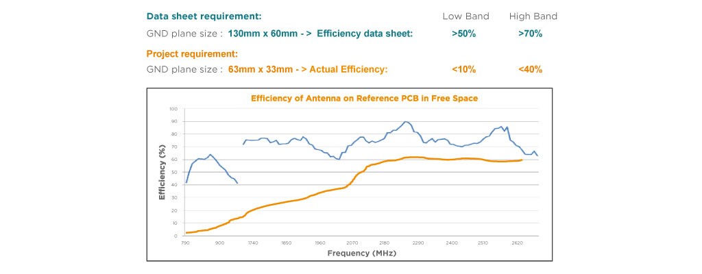
TE performed an in-depth analysis of Exelonix’s initial design, which used three onboard antennas (cellular, GNSS and Bluetooth) selected by datasheet values, size and applied cost. What the team uncovered was a typical issue in IoT devices related to inadequate ground plane size adversely impacting RF performance. The data sheet required a ground plane of 130 mm x 60 mm to deliver >50% low band performance and >70% high band performance. However, the project requirement specified a ground plane size of 63 mm x 33 mm, resulting in <10% efficiency on the low band, and <40% efficiency on the high band.
“While data sheets often show ideal performance results, in real life, antennas are surrounded by other components and materials. The size of the actual ground plane is often much smaller than the reference ground plane. Exelonix’s device required a significantly larger ground plane to deliver better efficiency of energy radiated out to the air, instead of being transformed to heat due to lossy material,” comments Christian Koehler, Senior RF Antenna Product Manager at TE.
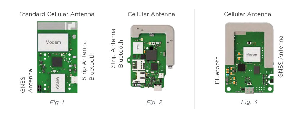
After the analysis was completed, TE’s engineering team began the prototyping design process and first attempted to modify the existing antenna (Fig. 1) or identify a better performing standard antenna that could offer a similar level of cost-effectiveness and production simplicity. The results showed inadequate GNSS performance as well as weak cellular performance in low bands.
The team then shifted toward a custom antenna concept (Fig. 2), incorporating best practices from the smart phone industry with a focus on improving bandwidth and efficiency using the third dimension. In the second stage of prototyping, the team developed an “L” shaped antenna block using laser direct structuring (LDS) technology. The block incorporated the cellular and GNSS antennas and delivered better performance with >20% efficiency in the worst case, but lacked integration of the antennas compatible with Bluetooth technology.
Building from that concept, the team developed a “U” shaped LDS antenna block (Fig. 3) that incorporated the cellular, GNSS and antennas compatible with Bluetooth devices, which yielded greater performance improvement with further distance to the ground plane and isolation of the antennas to minimize coupling and signal interference.
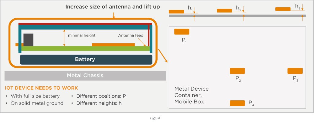
“While we were happy with the second concept, we had to take it to a real use case and evaluate distance, position and height on the board,” explains Koehler. He continues, “Underneath the PC board there was a battery that could impact efficiency and bandwidth of the antenna, so we had to increase the distance between the battery and the board. In addition, there was a metal chassis underneath the tracking device. The team then took the chassis as a use case example and placed the tracking device in different positions on the board (Fig. 4). We also applied different heights between the device and ground plane. It was amazing the impact on RF performance. P2 and H1 presented the most challenging use cases, so we took them as a benchmark to design the antenna properly.”
The Final Design
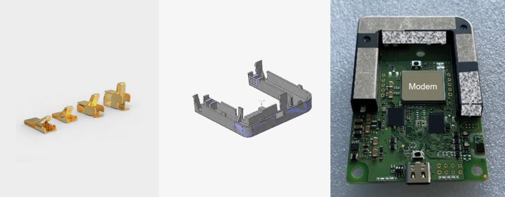
After an intensive use case testing process, the final design chosen was the U-shaped block antenna that incorporates cellular antennas, antennas compatible with Bluetooth devices and GNSS antennas with maximum ground plane distance. The cellular antenna (Fig. 5) is made with TE’s MetaSpan antenna technology, which provides a smaller form factor and helps prevent coupling with adjacent RF components or other antennas. Planar inverted-f antennas (PIFAs) were utilized for compatibility with Bluetooth technology and GNSS functions.
The design not only met Exelonix’s strict requirements, but also offers easy assembly and high repeatability for mass production. Hooks located on the bottom of the block easily clip directly into the PC board and antenna end feeds connect to spring clips, which are soldered onto the board surface.
Results
Through the joint efforts of TE and Exelonix, the final antenna design achieved an IoT form factor of 90 x 58 x 15 mm with an efficiency of >30%, which surpassed the certification limit of >20%. Weak GNSS performance increased up to 99.9% in the repeated tracking scenario and the number of messages to be transmitted with the battery capacity increased by a factor of nearly 10.
“We always strive to exceed expectations in time to market and end user satisfaction—not just with antennas, but withrelated connectors, sensors and board level shielding. This is what customers can expect from TE,” explains Koehler.

Having a great RF design is absolutely critical. Thanks to TE, we had a strong supplier to help us overcome our limitations. In the end, we received very good feedback from customers for the improvement from our proof-of-concept phase to the final product.
- Matthias Stege, managing director and founder at Exelonix