Read Insights about Energy industry


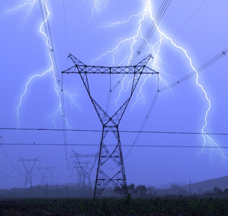

Grid Connectivity + Reliability
You need robust, safe, reliable networks that stand up to modern energy demands. So everything we do focuses on providing solutions that keep your grid connected and the power on. With over 60 years of experience and 2,300 employees around the world dedicated to the Energy industry, we understand your situation. Because grid connectivity and reliability matter, every connection counts – to you and to us.