Please review product documents or contact us for the latest agency approval information.
Product Type Features
-
Relay Type
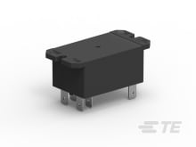
General Purpose Power Relay
Configuration Features
-
Coil Special Features
UL Coil Insulation Class F
-
Contact Arrangement
2 Form A DPST-NO, 2 Form C DPDT-CO
-
Contact Number of Poles
2
Electrical Characteristics
-
Contact Limiting Breaking Current (A)
40
-
Coil Power Rating DC (W)
1.7, 4
-
Coil Resistance (Ω)
9.1, 36.6, 86, 197, 350, 950, 1390, 2841, 3800, 5485, 7255
-
Coil Voltage Rating (VAC)
12, 24, 120, 208, 240, 277
-
Coil Voltage Rating (VDC)
12, 18, 24, 48, 110
-
Contact Current Rating (A)
20, 30
-
Contact Switching Load (Min)
500mA @ 12V
-
Contact Switching Voltage (Max) (VAC)
600
-
Contact Voltage Rating (VAC)
277
-
Insulation Initial Resistance (MΩ)
1000
-
Insulation Initial Dielectric Between Contacts & Coil (Vrms)
4000
-
Insulation Initial Dielectric Between Adjacent Contacts (Vrms)
1500
-
Contact Limiting Continuous Current (A)
40
-
Contact Limiting Making Current (A)
40
-
Insulation Initial Dielectric Between Open Contacts (Vrms)
1500
-
Coil Current (A)
.014, .015, .017, .019, .033, .035, .071, .077, .121, .14, .142, .167, .333
Body Features
-
Product Weight
86 g [ 3.034 oz ]
-
Enclosure Type
Plastic Dust Cover, Sealed
Contact Features
-
Contact Material
AgCdO, AgSnOInO
-
Contact Plating Material
AgCdO
Termination Features
-
Relay Connection Type
PCB Termination, Terminals
-
Terminal Configuration
Quick Connect Terminals, Screw Terminals, Solder Pins
Mechanical Attachment
-
Product Mount Type
Panel, Printed Circuit Board
-
Product Mounting Feature Type
Flange with Mounting Slots
Dimensions
-
Product Height (mm)
26.42, 30.73, 51.05
-
Product Height (in)
1.04, 1.21, 2
-
Product Length (mm)
52.32, 68.58
-
Product Length (in)
2.05, 2.7
-
Product Width
34.54 mm [ 1.36 in ]
-
Insulation Creepage Between Contact & Coil
8 mm [ .315 in ]
-
Insulation Clearance Between Contact & Coil
8 mm [ .315 in ]
Usage Conditions
-
Operating Temperature Range
-55 – 85 °C [ -67 – 185 °F ]
-
Environmental Ambient Temperature (Max)
85 °C [ 185 °F ]
-
Environmental Category of Protection
RTI, RTII
Operation/Application
-
Coil Magnetic System
Monostable
-
Current Type
AC, DC
Packaging Features
-
Packaging Method
Box & Tray, Bundle
Other
-
Contact Current Class (A)
30 – 50
-
Width Class (Mechanical) (mm)
30 – 40
-
Height Class (Mechanical) (mm)
25 – 30, 30 – 40
-
Environmental Ambient Temperature Class (°C)
70 – 85
-
Length Class (Mechanical) (mm)
50 – 60
Reference Number
-
TE Internal Number
CAT-P851-T1B