SEAT POSITION SENSOR FAQS
Product Overview
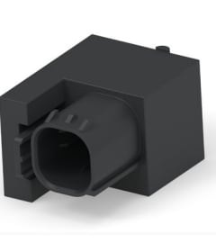
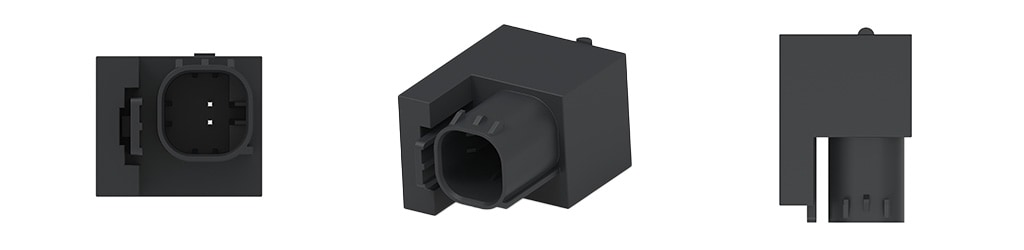
Seat Position Sensor
TE Connectivity’s (TE) seat position sensor uses a non-contact magnetic design with a zero Gauss reference point for precise metal target detection. Combined with a clip-in mount and wide air gap tolerance, it enables fast integration across seat architectures – at scale. The sensor delivers accurate, wear-free performance suitable for safety-critical applications, while its robust and customizable design adapts to a wide range of seat track configurations and vehicle platforms.
Can the seat position sensor to support 2-zone and 3-zone seat position detection?
Yes. The seat position sensor can be used individually for 2-zone detection or combined in a dual-sensor configuration to support 3-zone seat position detection, depending on system architecture and target placement.
How can a dual-sensor configuration be used to create 3-zone detection?
By placing two sensors along the seat rail and defining their detection zones through target geometry and spacing, OEMs and Tier 1s can establish rear, mid, and forward seat position zones. Each sensor provides a discrete signal, allowing the ECU to infer three distinct seat positions without requiring continuous position sensing.
Can the seat position sensor be adapted to different seat architectures or OEM requirements?
Yes. The sensor features a clip-on mounting design, flexible electrical interfaces, and configurable detection zones through target geometry. TE works directly with OEMs and Tier 1s to tailor placement, detection zones, and integration details to meet platform-specific requirements.
What is the required air gap between the sensor and the target?
The maximum allowable air gap between the sensor’s sensitive surface and the ferromagnetic shunt target is 4.6 mm when the sensor is flat and parallel to the target. For horizontal “slide-by” configurations, TE recommends keeping the air gap below 4.0 mm to provide additional margin.
What are the key placement constraints for the sensor on the seat rail?
Key placement considerations include:
- The sensor’s sensitive surface must be parallel to the shunt target
- The target must fully cover the sensor’s sensitive area across the intended detection range
- No external magnetic field sources (e.g., motors) should be placed within 75 mm of the sensor
- Only the mounting bracket should be in close ferrous proximity to the sensor
What materials are recommended for the shunt target?
The shunt target should be made from a ferromagnetic, magnetically inert material, such as ferrous steel, with an absolute remnant field density of less than 5 Gauss. Target dimensions and material directly influence switching behavior and must be validated at the system level.
What output signal does the sensor provide?
The sensor uses a current-based digital output:
- 5.0–6.9 mA when the sensor is over the target (ON state)
- 12–17 mA when the sensor is away from the target (OFF state)
What environmental and durability testing has the sensor undergone?
The sensor has been validated through extensive automotive-grade testing, including:
- Thermal cycling and thermal shock
- Random vibration and mechanical shock
- High temperature and high humidity endurance
- Water, salt spray, dust, and fluid exposure
- EMC and ESD testing per ISO, SAE, and CISPR standards
How does the sensor handle hysteresis and switching stability?
The sensor incorporates a defined hysteresis zone between approximately 4.6 mm and 10 mm from the target, preventing signal chatter during seat movement. System design should avoid powering the sensor within the hysteresis zone to ensure a valid output state.
Body Mounting Options
What is the minimum distance between the 2 sensors for them not to interfere with each other?
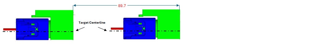
There are three typical positions to consider when evaluating interference between two sensors: face-to-face, back-to-back, and front-to-back. Minimum recommended spacing between sensor faces is shown below (mm).
Installation models are available for each mounting options upon request.
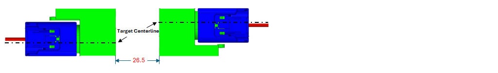
Face-to-Face Configuration
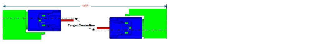
Back-to-Back Configuration
Front-to-Back Configuration
Samples and Product Support
How can I request samples?
Samples can be requested through your local sales representative or through our sample request page. Once processed, samples are shipped either to your location or to a local TE engineer or account manager for delivery.
Who should I contact for technical or commercial support?
For technical or commercial support, please contact your local account manager representative or submit the form to discuss available solutions, integration, architecture, and evaluation considerations with a sensor expert.