Rugged Performance, Smaller Size
Below are 5 steps engineers need to consider during the selection process for a rugged fiber optic connectivity solution
Choosing the right connector begins with understanding the 5 factors to consider when selecting a Rugged Fiber Optic (RFO) solutions. The first step is about the differentiation between physical contact and expanded beam technology. A second step of consideration is the application’s signal density requirement. Different solutions are available that respond to the need of higher density – especially inside the box for VPX embedded systems. The third step is the choice of the right termini in order to minimize insertion loss (IL) and back reflection. The forth step should be about connector materials, form factors and sizes that best suit the application. In a fifth step the best cable option needs to be chosen. Again, various options are available depending on the application and whether cables are being routed within a box or between boxes or active devices in limited spaces.
5 Key Factors for Choosing Rugged Fiber Optic Solutions
1. Understanding Fiber Optic Connector Technologies
As with any project involving electronics, the kinds of components selected depend on the performance criteria the project is trying to meet. There is no single solution that will always work in every situation. Therefore, its important to understand the tradeoffs between different technologies when aiming at your performance target.
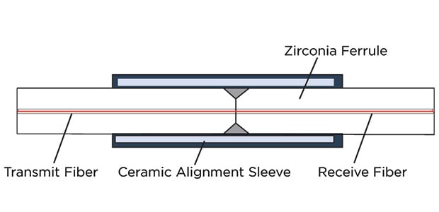
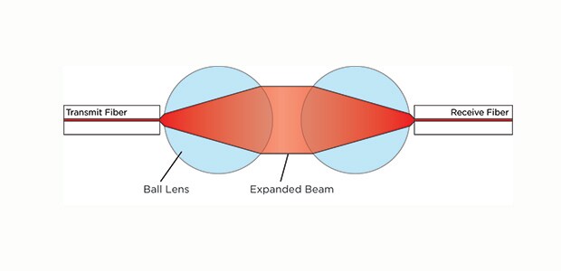
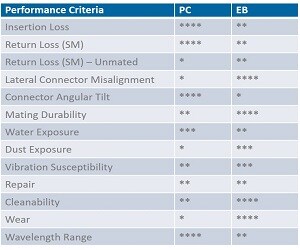
Fiber optic connectors are used to couple a light source, receiver, and other components to a fiber optic cable. Of the many types of fiber optic connectors, each generally employs one of two connection technologies: physical contact (PC) technology that physically mates the two ends of optical fibers together or expanded-beam (EB) technology that uses lenses at fiber end-faces to expand and refocus light within a small air gap in the optical pathway
When selecting between the two types, considerations include environmental variables such as exposure to water, dust, and vibration; termination finishes in terms of insertion loss, return loss, misalignment, and angularity; maintainability with regard to repair, cleanability, and wear; and cable limitations such as bend radii and wavelength range. Clearly understanding your operating environment and your signal power budget is critical to connector selection. PC fiber optic connector technology excels at minimizing insertion loss (IL) and return loss (RL) while maximizing wavelength range. On the other hand, EB connectors are more tolerant of misalignment, vibration, dust, and wear because the small gap in the optical pathway eliminates the need to maintain pristine physical contact.
2. Evaluating Signal Density Requirements
Another high-level consideration is the application's signal density requirements. Today, there is a real push for higher density — especially inside the box for VPX embedded systems. For 110 between boxes, there's demand for high fiber path count through small 38999 connectors. Single fibers and single contacts increasingly can't be used, because there just isn't enough space to aggregate them to create multiple paths. The alternative is to group them in a ribbon and terminate them in a multiple fiber ferrule, more widely known as a mechanical transfer (MT) ferrule connector.
In the commercial datacom world, MT fiber optic ferrules provide super-high-density interconnects that accommodate 12 to 96 fibers in a compact and lightweight ferrule. MT ferrules deployed in VPX applications in harsh environments typically have 12 or 24 fibers per ferrule, resulting in up to 48 fiber paths in a half VPX module. There are also MIL-DTL-38999 Series III based expanded beam connectors available that provide self-locking anti-vibration coupling mechanism for up to 96 optical channels. With these solutions, you can get the best of both worlds — high signal density and harsh-environment performance.
3. Selecting the Right Termini for Optimal Performance
How the connector is terminated is important in reducing insertion loss (IL) and back reflection. For PC fiber optic connectors, two basic polishing approaches can be used. Flat polished surfaces for PC and ultra-physical (UPC) contacts are generally acceptable for digital optical traffic. But for optical sensing applications, such as light detection and ranging (LiDAR) and radio frequency (RF) over fiber applications, return loss (RL) needs to be minimized. In these cases, angle polished ferrules (APC) are used to minimize RL.
For LB connectors, the lack of physical contact reduces mating forces. Because lower or no spring force is required, LB connectors maintain consistent IL over multiple mating cycles. They also offer enhanced robustness in harsh and dirty environments — but at greater expense. That's because with LB connectors, subcomponents and ceramics must be combined with proper termination and polishing procedures. The contacts inherently involve lenses as well, which adds further cost. However, when properly constructed. LB connections can yield consistent IL values less than 1.0dB
The same polishing/performance rules apply to MT ferrules, which are molded as flat (typically for multimode fiber) or APC (typically for single mode fiber) configurations. In terminating these various designs, changing the polishing fixtures is the main difference. Lensed MTs (EBs) typically have the lens molded into the ferrule, so no polishing step is required, but you have to cleave the ribbon fiber precisely.
4. Choosing the Best Connector Materials, Form Factors, and Sizes
The ferrule the rigid tube used to protect and align the end of a fiber — is a very critical connector component. Fiber optic ferrules can be made of ceramic, metal, or composite materials. Generally, fiber ferrules for PC connectors are made from ceramic or metal materials. Each material has its benefits and drawbacks. Ceramic or metal ferrules are typically used for harsh-environment applications.
Ferrules are supported in inserts, which also come in a range of metal, composite, and polymer materials. Trade-offs are typically lower weight versus higher durability, materials compatibility with various fluids, and, in some cases, the need to incorporate face seals on the inserts.
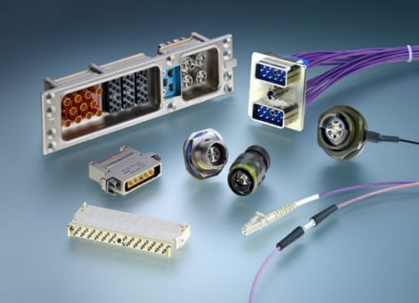
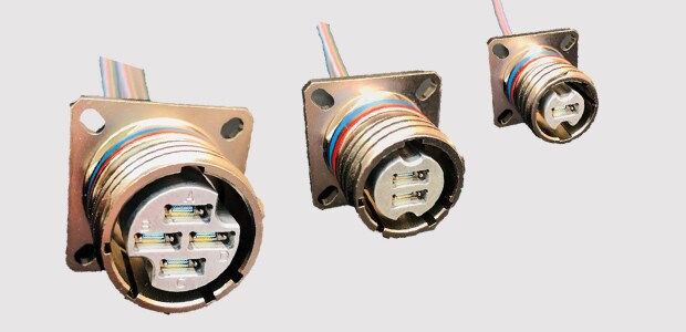
Various connector form factors are available, namely rectangular and D38999 circular styles with metal and composite shells, inserts, and related components. Typically, the shells and other components used are the same as with copper versions. The inserts, however, are dedicated to fiber optic contacts or in some cases hybrid (i.e., copper and fiber optic) contacts. The latter is typically only used in low-mating applications because oxides from copper can contaminate the fiber optic termini
5. Exploring New Cabling Options for Rugged Applications
A fiber optic cable consists of five main components: core, cladding, coating, strengthening fibers, and cable jacket. Cabling considerations are influenced by whether cables are being routed within a box or between boxes or active devices in limited spaces.
As mentioned, multiple fiber ribbon cables can accommodate multiple paths. Moreover, ribbon cable can be broken out into individual contacts. This is often the case between MT ferrules on the VPX backplane to the I/O box connector in those instances where traffic routes to multiple locations or the end points.
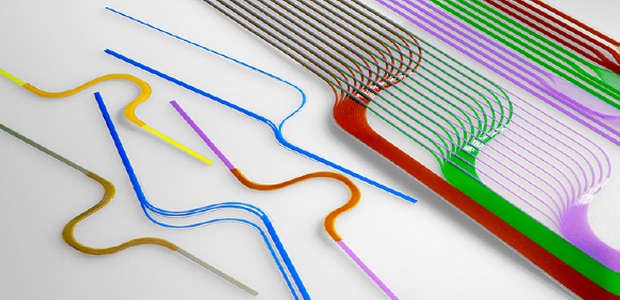
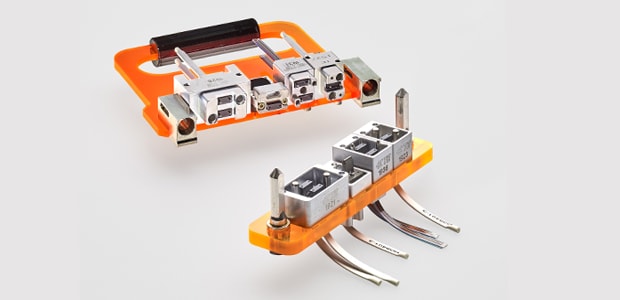
Optical flexible circuit assemblies (FCAs) are an advanced version of flexible flat ribbon cables (FFCs). Comprised of hundreds, or even thousands, of individual fibers precisely positioned on a single rugged substrate. FCAs offer a multifiber management solution for high-speed electronic packaging. FFC advantages include:
• Full customizability for both card-to-card and backplane applications. For example, one defense application is currently using a 3,000-path FCA.
• Ruggedized fibers with thin film encapsulation for protection in harsh-environment aerospace, commercial and military aircraft, and defense systems.
• Versatility of employing crossovers to minimize stress while fitting complex routing arrangements.
• High backplane-level speeds between two processor cards with all the I/O coming off a parallel transceiver through the FFC operating just as fast as a backplane. Moreover, new material sets are becoming available to handle space applications as well as traditional aerospace and defense (A&D) applications with stringent radiation-hardening and volatile organic compound requirements. For more information about rugged fiber connectors for harsh environments, visit TE Connectivity online store