Industries
Battery Pack Connectors
An introduction to battery connector configurations and terminology.
As the size of mobile equipment shrinks and affects the space available for battery packs, the need to balance current carrying capabilities, provide higher amps, and support quicker charging times becomes more important. Our portfolio of products supports the various requirements for design engineers and provides what is necessary for reliable connections between a main PCB and a battery pack.
Related Products
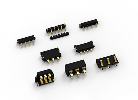
Mating Battery Connectors

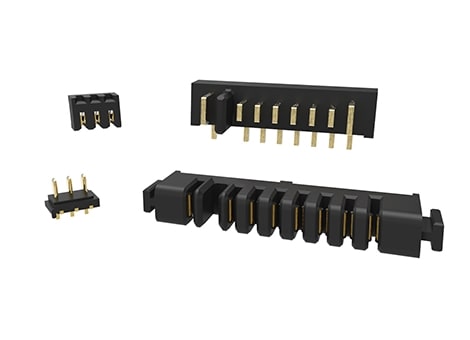
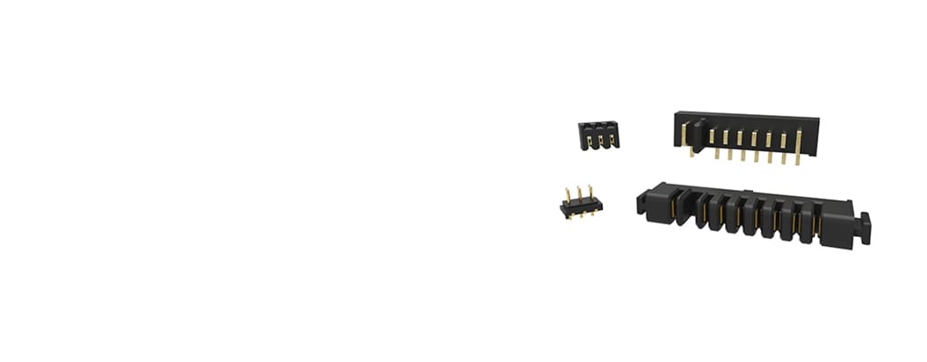
Choosing the right battery connectors is critical to creating a reliable solution. Parts can be mated with boards that are coplanar, parallel, or perpendicular. When you make your selection, refer to the drawings to confirm that the length of all pins and sockets does not exceed its mating counterpart. To determine where the voltage key is located, look at the PCB. The connector faces downward on the edge of the PCB. (Refer to the following images and the recommended PCB layout in the customer drawing.)
Mating Configurations
The number of pins must be equal to the number of mates. The following tables shows the combinations of plug attributes that mate with the receptacle attributes. Choose products with corresponding attributes.

1.) Coplanar
When both plug and receptacle are mated, the PCBs are on the same plane.
| Connector Type | Mount Angle |
PCB Mount Style |
Voltage Key | Mate ↔ |
Connector Type | Mount Angle |
PCB Mount Style |
Voltage Key |
|---|---|---|---|---|---|---|---|---|
| Plug | R/A | TH or SMT | Left (X Pins) |
↔ | Receptacle | R/A | TH or SMT | Right (X Pins) |
| Plug | R/A | TH or SMT | Right (X Pins) |
↔ | Receptacle | R/A | TH or SMT | Left (X Pins) |

2.) Parallel
When both plug and receptacle are mated, the PCBs do not intersect.
| Connector Type | Mount Angle |
PCB Mount Style |
Voltage Key | Mate ↔ |
Connector Type | Mount Angle |
PCB Mount Style |
Voltage Key |
|---|---|---|---|---|---|---|---|---|
| Plug | R/A | TH or SMT | Left (X Pins) |
↔ | Receptacle | R/A | TH or SMT | Left (X Pins) |
| Plug | R/A | TH or SMT | Right (X Pins) |
↔ | Receptacle | R/A | TH or SMT | Right (X Pins) |
| Plug | Vertical | TH or SMT | Left (X Pins) |
↔ | Receptacle | Vertical | TH or SMT | Left (X Pins) |
| Plug | Vertical | TH or SMT | Right (X Pins) |
↔ | Receptacle | Vertical | TH or SMT | Right (X Pins) |

3.) Perpendicular
When both plug and receptacle are mated, the PCBs meet at a right angle.
| Connector Type | Mount Angle |
PCB Mount Style |
Voltage Key | Mate ↔ |
Connector Type | Mount Angle |
PCB Mount Style |
Voltage Key |
|---|---|---|---|---|---|---|---|---|
| Plug | R/A | TH or SMT | Left (X Pins) |
↔ | Receptacle | Vertical | TH or SMT | Left (X Pins) |
| Plug | R/A | TH or SMT | Right (X Pins) |
↔ | Receptacle | Vertical | TH or SMT | Right (X Pins) |
| Plug | Vertical | TH or SMT | Left (X Pins) |
↔ | Receptacle | R/A | TH | Left (X Pins) |
| Plug | Vertical | TH or SMT | Right (X Pins) |
↔ | Receptacle | R/A | SMT | Right (X Pins) |
Power Terminology
Current Carrying Capacity
Refers to the maximum current an insulated conductor is capable of carrying without exceeding its insulation or jacket temperature limitations under specified ambient conditions.
T-Rise
Refers to the change in temperature of a terminal from a no-load condition to full-current load. TE products are tested at 30 degrees Celsius per EIA 364-70A / IEC 60512-5-1.
De-rating
Refers to the specified reduction in output power required for operation at elevated temperatures. De-rating is necessary when loading multiple contacts between a system and battery pack.

Example of Pin Functions - Battery pack interconnects typically require the flow of power both into and out of the system to the battery pack. For example, if you use an eight-position connector, there are three pins reserved for power flowing out of the system to the battery pack and another three pins for flowing power from the battery pack into the system. Normally, there are a few pins reserved for both grounding (circled right) and signal requirements (center pin) with the keying feature in black (circled left).
Keying Feature
A keying feature is a mechanical arrangement that allows connectors of the same size and type to be mated.
Grounding Pin
The longest pin is typically used as a conductor that provides a return path for the current from an electrical device to ground.
Current Rating
The maximum carrying capacity of a battery pack connector cannot simply be calculated by multiplying the maximum current per pin by the number of contacts. The maximum current listed in TE’s 108 specifications is for a single contact. Therefore, when many contacts are used to transfer power, the maximum current carrying capacity of each individual contact decreases as more than one contact is used to transfer power.
Example
The example assumes one contact can carry seven amps. The total current is for both in and out power, so to calculate the one-way maximum current, divided the total current by two.
Current ratings are based on the same equivalent wire gauge for both the header and the battery housing contacts. Equivalent wire gauge means that the current rating of the conductor is equivalent to that of copper wire. Such a conductor could be the copper PCB traces for the header assembly contacts or conductive strips used for battery housing assembly contacts.
| Loaded Contacts |
Current/Pin (Derated) |
Total Current |
|---|---|---|
| 1 | 7 | 7 |
| 2 | 6.8299 | 13.6598 |
| 3 | 6.1754 | 18.5262 |
| 4 | 5.572 | 22.288 |
| 5 | 5.0134 | 25.067 |
For example, if a PCB trace is desired for only one header assembly contact requiring a current rating of seven amps, one can refer to EIA RS-214 to find out if a 0.4mm2 equivalent wire gauge is necessary for a 30 degrees Celsius temperature rise above ambient. The example above uses a 1.57mm PCB. Additional de-rating of 15 percent (current wise) is advised for PCB thickness of 0.8 mm or less, and for conductor thickness of 0.108mm or more.
Frequently Asked Questions
What is sequencing?
The process of performing a series of operations in a predetermined order. Longer blade contacts enable you to sequence your operations.
What questions should I ask when designing-in battery pack connectors?
Understanding the product attributes will help you understand the best TE solution for your application. The most important physical attributes are number of positions, connector type, mount angle, PCB mount, voltage key, PCB mount retention, locating boss, and XYZ dimensions. It is also important to collect the total current needed between the system and battery pack, the durability mating cycles, and the operating temperature.
Where can I find more information about battery pack connectors?
You can find additional information about our standard battery pack connectors at www.TE.com/products/batterypack. You can order samples through our sample system on the Part Details page.