Q: What is the most common type of platinum RTD element?
A: The Pt100 is the most common type of platinum resistance temperature detector (RTD) element. The base resistance value for a Pt100 RTD is 100Ω at 0°C (ice point) and they are available in thin-film or wirewound versions.
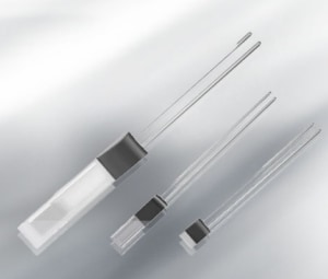
Q: The platinum thin film elements are offered in a variety of sizes, which one do I choose?
A: There are four standard sizes available (LxWxT):
- PTFC outline: 2.0 x 2.3 x 1.1mm
- PTFD outline: 2.0 x 5.0 x 1.1mm
- PTFF outline: 2.0 x 4.0 x 1.1mm
- PTFM outline: 1.2 x 4.0 x 1.1mm
Typically, for a new design we would recommend the PTFC outline due to its relatively low unit price and versatility to fit into a variety of housings for value-added probes and assemblies. Based on your design requirements, we have other sizes available that allow for smaller outline dimensions, where size or time response is critical. We also have options for applications that utilize a larger size or require more power, the table below summarizes some of the characteristics based on the size of the element.
| Smaller Element | Larger Element |
|---|---|
| Faster response time | Slower response time |
| Larger self-heating coefficient | Smaller self-heating coefficient |
| Lower recommended measuring current | Less self-heating error at the same power |
| Fits into housings with smaller area | Has a larger contact area for sensing |
Q: What is a self-heating coefficient?
A: The self-heating coefficient defines the amount of self-heating or rise in temperature for the element based on the amount of power through the element. This rise in temperature is not desirable, as it will potentially introduce errors into the temperature measurement.
For example, the PTFD outline has a self-heating coefficient in air flowing at 1 m/s of 0.33°C/mW which means that for each mW of power through the device will cause a rise in the temperature of the element of 0.33°C beyond the ambient temperature.
A rule of thumb is that self-heating errors should be limited to no more than 10% of the desired accuracy. So for example, a PTFD element with a Class A tolerance class, would have an accuracy of ±0.15°C at 0°C. Therefore, the error from self-heating should be limited to 0.015°C which would imply power be limited to ±0.015°C / 0.33°C/mW = 0.045mW.
Since power for a resistive element like an RTD is equal to I2R, Max I = SQRT(0.045mW/100Ω) for a Pt100 element or .0213A or 21.3mA.
Q: What is TCR and how is it calculated?
A: Thermal coefficient of resistance, also known as TCR, is the average resistance increase per K of hypothetical RTD measuring 11Ω at 0°C. TCR is is similar to alpha (α) which is generally associated with thermistors. TCR is the average change in resistance between 0°C and 100°C and is calculated using the formula:
TCR=(R100-R0)/(R0*100)°C
Q: How do I calculate the resistance for Pt thin film elements at temperatures other than 0°C?
A: The calculation formula for a platinum RTD element is defined in DIN EN 60751 and is as following:
For T ≥ 0 °C: RT = R0 * (1+a * T + b * T2)
For T < 0 °C: RT = R0 * [1+a * T + b * T2 + c * (T-100°C) * T3]
Coefficients: a = 3.9083E-03 b = -5.775E-07 c = -4.183E-12
Q: What is the temperature tolerance at temperatures other than 0°C?
A: The accuracy for these RTD elements is defined in DIN EN 60751 and follows the formulas listed below:
| Tolerance Class | Interchangeability | Temperature Range Tolerance |
|---|---|---|
| F0.1 (T=AA); | ± (0.1+0.0017*|T/°C|) °C | (-30 … +200 °C) |
| F0.15 (A) | ± (0.15+0.002*|T/°C|) °C | (-30 … +300 °C) |
| F0.3 (B) | ± (0.3+0.005*|T/°C|) °C | (-50 … +600 °C) |
| F0.6 (C=2B) | ± (0.6+0.007*|T/°C|) °C | (-50 … +600 °C) |
Where |T/°C| is the absolute value of the temperature in °C
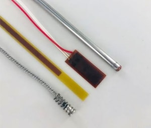
Q: What is the difference between "gold coated nickel wire" and "silver wire" leadwire types?
A: The Au-coated Ni wire allows for operation over the entire temperature range up to 600°C, while the Ag wire is limited to operation up to 300°C. The Au-coated Ni wire is typically used when the connections to the element will be made via welding or brazing while the Ag wire is better suited for soldering.
Q: Can the elements be operated outside of the temperature range noted for each accuracy class?
A: The Pt thin film elements are all manufactured using the same materials and processes, but they are tested and calibrated based on their corresponding accuracy class. That means that every element can operate over the full range from -200°C to +600°C (for Au-coated Ni wire) but, if the element is operated outside of the accuracy temperature range, the calibrated accuracy can not be guaranteed.
For example, class A (F0.15) accuracy class elements are calibrated to the accuracy defined in DIN EN 60751 over the temperature range from -30°C to +300°C. Operation outside of that range will not damage the element, but it may cause slight shifts in the part’s calibration and the original accuracy specifications can no longer be guaranteed.
Q: What specifications apply for platinum thin film elements?
A: The platinum thin film (PTF) family is designed and manufactured to meet the DIN EN 60751 specification.
- IEC 60751 and ASTM E1137 specifications are very similar.
- IEC 60751 and DIN EN 60751 specifications are identical.
- The DIN specification is basically the IEC specification with an additional cover page.
- The DIN EN 60751 and the ASTM E1137 are very similar as both specifications apply to the standard 3850ppm/K temperature coefficient platinum curve and are based upon the ITS-90 temperature scale. One primary difference between the two specifications is the definition of tolerance classes, as follows:
| DIN EN 60751 | ASTM E1137 | ||
|---|---|---|---|
| Tolerance Class | Tolerance Definition | Tolerance Class | Tolerance Definition |
| Class F0.3 (Class B) | ±(0.3 + 0.005 |T|) | Grade B | ±(0.25 + 0.0042 |T|) |
| Class F0.15 (Class A) | ±(0.15 + 0.002 |T|) | Grade A | ±(0.13 + 0.0017 |T|) |
Where |T| is the absolute value of the temperature in °C.
Q: Is there an ability to create a custom packaging for the assembly, in addition to the element?
A: Yes, TE Connectivity specializes in valued added probes and assemblies and does offer a number of standard and custom RTD assemblies that can be manufactured to match the exact needs of a customer. The assembly can consist of something as simple as an added piece of heat shrink tubing over the element along with larger AWG# extension leads; to fully ruggedized assemblies with metal housing, extension leads, encapsulants and connectors. Learn more about RTD Probes & Assemblies.