Achieve the longest possible life from relay contacts
What precisely is an electric arc? How does it ignite and what causes it to extinguish? How does an arc affect the life of relay contacts?
These are some of the questions that we will discuss here. We hope to help you better understand how to obtain the longest life possible from relay contacts such as these.
But first, let’s take a minute to define a few of the terms we’ll be using.
First of all, “constriction” refers to the very first, tiny area of contact surface to make, and the very last point to break.
Melt Voltage is that amount of voltage that exists across the constriction which will cause a current sufficient to liquify the contact material at the constriction.
Arc Voltage is that amount of voltage that exists on contacts separated by a small gap that will cause an electric discharge across the gap.
And, lastly, Arc Current is that amount of current necessary to just sustain an arc caused by the arc-voltage electric discharge.
Now, keep these terms in mind as we take you into the world of relay contacts—a fairly harsh environment. Let’s take a microscopic look at the effects of contact arcing.
As you know, the end result of contact arcing is shortened contact life. Depending on the severity and duration of the arc, each time an arc ignites, contact erosion occurs. This erosion causes a loss of contact material which will result in one of two conditions.
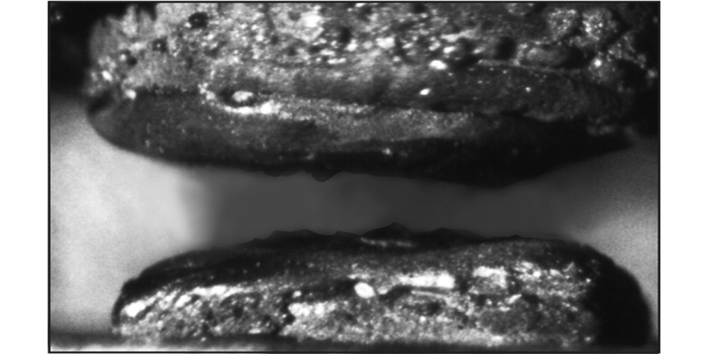
Figure 1. Condition #1
Condition #1 is where so much material is lost from the contacts that they fail to electrically close the load circuit. Condition #2 is where one contact loses so much material to the other contact that a spike-and-crater results.
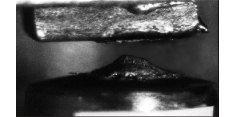
Figure 2. Condition #2
Important note about synchronization in AC load switching
The term Synchronization, relating to AC load switching, is used several times in this application note. In this context, synchronization is operation of a relay such that the contacts make or break (or both) at the same point on the load supply voltage waveform, or primarily at the same polarity on the load voltage sine wave.
Such synchronization will result in net transfer of contact material between contacts. This increases the probability of mechanical locking and/or welding of contacts, and thus reduces expected contact life. All our published ratings and life test results are based on random switching relative to the load supply frequency, unless otherwise specified.
Inadvertent synchronization of the contacts to line frequency can be caused by, but is not limited to, the following scenarios:
- Microcontrollers synchronized to power supply frequency
- Thyristors synchronized to power supply frequency
- Insufficient filtering of the DC power supply which drives the coil
- Induced line frequency noise in sensor circuits
Exercise caution in circuit design, as an intended “zero cross” circuit which is improperly designed can result in contact closure, and especially bounce, during higher current flow and at the same polarity.
Another result of severe arcing which may occur now and then is contact welding. Usually, though, when this happens, it is evidence that the relay has been misapplied in a circuit where voltage and/or current are much greater than that particular relay can handle.
Regarding a spike-and-crater condition, when the condition gets severe enough, the high spot—that is, the spike—may mechanically hang up on the rim of the crater. Then when the relay is deenergized, the contacts fail to open, and the load is in an uncontrolled-on condition. Needless to say, this is an undesirable situation.
Typically, a spike-and-crater material transfer condition is associated with a direct current application. But we are beginning to notice that even in some alternating current applications, spike-and-crater material transfer is evident.This is because, in these applications, the relays are being operated in synchronization with the AC line voltage. This synchronization usually is the result of the synchronization to the AC line of the solid state logic or microcomputer circuitry that operates the relay. If synchronization just happens to occur at or near line voltage peak, then each time the relay contacts operate, they do so at or near either 170 volts or 340 volts, depending, of course, on whether line voltage is 120 or 240 volts.
If the application requires that the circuit clock be synchronized to the AC line, additional circuitry should be included to effect random operation of the relay. Or, synchronization might be set that the relay contacts open at or near current zero.
Just one further comment here regarding spike-and-crater material transfer. Don’t automatically assume this type of transfer is the result of contact arcing. It may not be. Even in circuits in which no arc ignites, material transfer may occur. This is because the circuit voltage is greater than the melting voltage of the contact material and when the contacts just come together or just separate, the material melts, travels from the hotter contact, the anode, to the cooler contact, the cathode, and remains there. In an AC application where operation is truly random, material transfers first one way one time and the other way another time. The net result is no appreciable gain of material by either contact. But in a DC application or in an application where the relay is synchronized to the AC line, material transfer is always in the same direction and a spike-and-crater condition may result.
When an arc ignites, material transfer is from cathode contact to anode contact. Therefore, in any given operationof the contact, before an arc ignites, material transfers from anode to cathode, and then when the arc ignites, material transfers from cathode to anode. The amount of transfer is usually greatest during the arc. Keep in mind, though, as just explained—and this is important—in a truly random AC application, the net material gain of either contact is negligible, while in a DC application or in an application synchronized to the AC line, there may be significant material gain by one contact.
Now, let’s take a look at just what happens on contact closure. If you could examine the surface of a relay contact under a high power microscope, you’d see that the surface is quite irregular, consisting of deep low spots and a lot of high spots— with some spots higher than the others.

As the contacts just come together, the first high spot to make contact is subject to full load current. If load current is even a fraction of an ampere, the I2R heat generated in this high spot instantly causes the high spot to melt and perhaps even boil. The air surrounding the high spot is superheated and begins to ionize by the loss of electrons. If I2R energy is sufficient, the high spot may reach a temperature of 5,000 Kelvin or more and may explode, leaving superheated, ionized air and metallic ions in the gap between the contacts. Depending on contact material and the voltage stress on this air gap that is, the contact voltage at the instant of the explosion the ionized air gap may begin to conduct electron current from cathode to anode. This electric discharge between contacts is actually the beginning of an arc. If load current is in excess of the arc current rating of the contact material, the arc will contain sufficient energy to sustain itself. If not, the discharge between contacts will not cause arc ignition.
If an arc ignites, due to the Thompson effect there is a temperature gradient along the arc column, with the cathode being the hotter contact. That is, heat will flow from cathode to anode. The cathode spot in which I2R heat is greatest may boil, thereby giving off atomic and even molecular emissions. These emissions are pulled through the arc column and deposited on the slightly cooler anode contact. This, of course, is the principle of arc wielding. All of this happens in perhaps ten nanoseconds or more as the contacts continue to move together.
The arc exists until the next high spot or high spots make. Again, the heat in these high spots may cause them to melt. When they do, they begin to spread out, increasing the area of contact make. As the contacts move together forcefully, this liquified metal may spatter, resulting in a loss of material. As the molten metal between the contacts cools, the contacts are frozen together in the normal manner. Unlike the catastrophic weld which may occur when a relay is misapplied, this weld is weak and easily broken by the action of the relay spring forces when the relay is deenergized. Now, think back! What actually had to happen before the arc could ignite? Was load current or voltage responsible for the arc? Well, certainly the arc must have a medium through which to travel, and the ionized gap between the contacts is that medium. And certainly it was load current heating of a contact high spot which caused the ions. But it was the voltage that existed across the contact gap that resulted in arc ignition. This voltage need not be load voltage. It may be circuit voltage. That is, upon contact make, there may be a certain amount of capacitance in the circuit that will charge through the contacts.
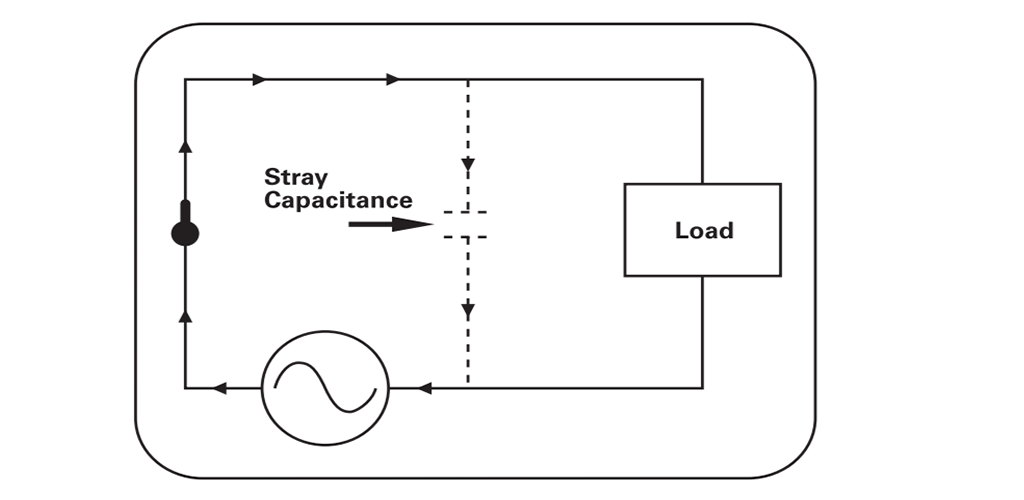
Also, if an arc-suppression capacitor is used across the contacts, this capacitance will discharge itself through the relay contacts.
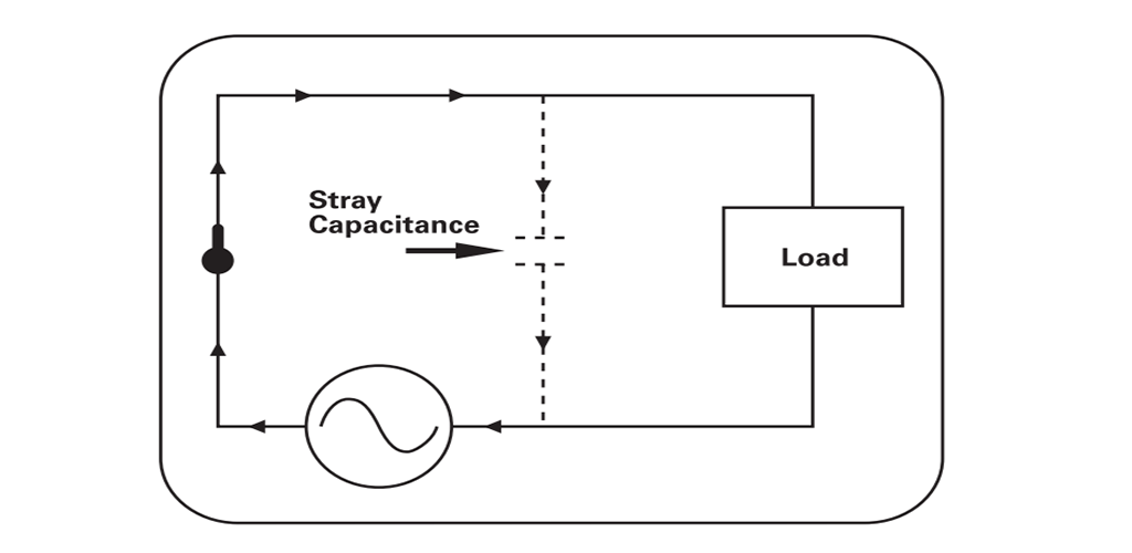
The discharge surge current may be hundreds of amperes for a few nanoseconds or more. To limit such discharge currents, an arc-suppression capacitor should have a certain amount of resistance in series with it. In circuits where there is no dedicated capacitance, however, there still may be sufficient stray capacitance to cause a momentary overcurrent upon contact make. This fact is often overlooked by many circuit designers.
An arc ignites in similar manner upon contact break. As the contacts begin to separate, less and less contact area carries load current. Load current begins to funnel into this constricted area and I2R heat begins to increase. The very last point of contact melts and, as the contacts continue to separate, a thin bridge of molten metal is stretched between the contacts. The air in the gap begins to ionize. The I2R energy in the bridge generates so much energy that the bridge literally explodes, showering the gap with metallic ions. Again, if contact voltage is sufficient, an arc will ignite.
Different contact materials have different arc voltage ratings. For fine silver, the arc voltage is 12 volts. For cadmium, it is 10 volts; and for gold and palladium it is 15 volts. Let’s assume the contacts are fine silver. Within nanoseconds after the molten bridge explodes, if the material is silver and if circuit voltage is 12 volts or more, voltage breakover occurs. If circuit voltage is less than 12 volts, breakover cannot occur and there will be no arc.
When an arc ignites between separating contacts, it will be sustained as long as there is sufficient energy to feed it. As long as the arc exists, material transfer will continue. In a direct current application, the arc can be extinguished only by stretching it to such a length that its own impedance causes it to extinguish, or by opening the circuit at some other point. In many applications, though, the contact gap is wide enough that the arc will extinguish before the contacts have fully opened. It is for this reason that relays of a given contact rating will be rated for, say, 120 volts AC, but will have a considerably lower DC voltage rating—usually 28 or 30 volts DC. That is, the gap is wide enough that, given the periodic swing through zero of alternating current, any AC arc should quickly extinguish. But the gap would not be wide enough for a 110 volt DC arc to extinguish.
In an AC application, depending on the temperature of the ionized air, even though arc current decreases to zero every half-cycle, the arc may reignite after current zero.This is because positive ions still exist between the contacts and it doesn’t require much energy to reignite the arc.
It has long been recognized that, compared with fine silver, silver-cadmiumoxide contacts yield superior life in the presence of an arc. One theory says that since oxide coated materials produce negative ions when heated sufficiently, the negative ions produced by silver-cadmium oxide cause early recombination of the positive ions after current zero. This recombination causes the arc to extinguish earlier and may prevent reignition after current zero. This would seem to indicate that in an AC application where arcing is to be expected, silver-cadmium-oxide contacts protected with an appropriate arc suppression method should yield good contact life. We won’t get into arc suppression techniques here because that’s the subject of another application note titled “Relay Contact Protection.” All we will say about arc suppression here is that appropriate suppression can result in lengthened contact life. Additionally, by suppressing the arc, electromagnetic interference—EMI, for short—is held to a minimum. EMI is the result of atomic action in the arc column. In an arc plasma, the surface of the contacts is bombarded by atoms, positive and negative ions and electrons, some of which may be accelerated by passing through the electric field, and some of which may cause secondary emission of electrons which may radiate energy across a wide spectrum of frequencies. By quenching the arc quickly, this action is held to a minimum. The result often is a considerably lessened amount of electro-magnetic and radio frequency interference.
In summation, to achieve the maximum life from arcing relay contacts, proper relay and contact application and the possible use of arc suppression are most important.
Beware of AC applications where the relay is synchronized to the AC line voltage. If synchronization is unavoidable, set the clock so that relay contact operation occurs at or near zero current.
And, when severe arcing conditions are expected, select a relay having silvercadmium contact material.
Achieve the longest possible life from relay contacts
What precisely is an electric arc? How does it ignite and what causes it to extinguish? How does an arc affect the life of relay contacts?
These are some of the questions that we will discuss here. We hope to help you better understand how to obtain the longest life possible from relay contacts such as these.
But first, let’s take a minute to define a few of the terms we’ll be using.
First of all, “constriction” refers to the very first, tiny area of contact surface to make, and the very last point to break.
Melt Voltage is that amount of voltage that exists across the constriction which will cause a current sufficient to liquify the contact material at the constriction.
Arc Voltage is that amount of voltage that exists on contacts separated by a small gap that will cause an electric discharge across the gap.
And, lastly, Arc Current is that amount of current necessary to just sustain an arc caused by the arc-voltage electric discharge.
Now, keep these terms in mind as we take you into the world of relay contacts—a fairly harsh environment. Let’s take a microscopic look at the effects of contact arcing.
As you know, the end result of contact arcing is shortened contact life. Depending on the severity and duration of the arc, each time an arc ignites, contact erosion occurs. This erosion causes a loss of contact material which will result in one of two conditions.
Figure 1. Condition #1
Condition #1 is where so much material is lost from the contacts that they fail to electrically close the load circuit. Condition #2 is where one contact loses so much material to the other contact that a spike-and-crater results.
Figure 2. Condition #2
Important note about synchronization in AC load switching
The term Synchronization, relating to AC load switching, is used several times in this application note. In this context, synchronization is operation of a relay such that the contacts make or break (or both) at the same point on the load supply voltage waveform, or primarily at the same polarity on the load voltage sine wave.
Such synchronization will result in net transfer of contact material between contacts. This increases the probability of mechanical locking and/or welding of contacts, and thus reduces expected contact life. All our published ratings and life test results are based on random switching relative to the load supply frequency, unless otherwise specified.
Inadvertent synchronization of the contacts to line frequency can be caused by, but is not limited to, the following scenarios:
- Microcontrollers synchronized to power supply frequency
- Thyristors synchronized to power supply frequency
- Insufficient filtering of the DC power supply which drives the coil
- Induced line frequency noise in sensor circuits
Exercise caution in circuit design, as an intended “zero cross” circuit which is improperly designed can result in contact closure, and especially bounce, during higher current flow and at the same polarity.
Another result of severe arcing which may occur now and then is contact welding. Usually, though, when this happens, it is evidence that the relay has been misapplied in a circuit where voltage and/or current are much greater than that particular relay can handle.
Regarding a spike-and-crater condition, when the condition gets severe enough, the high spot—that is, the spike—may mechanically hang up on the rim of the crater. Then when the relay is deenergized, the contacts fail to open, and the load is in an uncontrolled-on condition. Needless to say, this is an undesirable situation.
Typically, a spike-and-crater material transfer condition is associated with a direct current application. But we are beginning to notice that even in some alternating current applications, spike-and-crater material transfer is evident.This is because, in these applications, the relays are being operated in synchronization with the AC line voltage. This synchronization usually is the result of the synchronization to the AC line of the solid state logic or microcomputer circuitry that operates the relay. If synchronization just happens to occur at or near line voltage peak, then each time the relay contacts operate, they do so at or near either 170 volts or 340 volts, depending, of course, on whether line voltage is 120 or 240 volts.
If the application requires that the circuit clock be synchronized to the AC line, additional circuitry should be included to effect random operation of the relay. Or, synchronization might be set that the relay contacts open at or near current zero.
Just one further comment here regarding spike-and-crater material transfer. Don’t automatically assume this type of transfer is the result of contact arcing. It may not be. Even in circuits in which no arc ignites, material transfer may occur. This is because the circuit voltage is greater than the melting voltage of the contact material and when the contacts just come together or just separate, the material melts, travels from the hotter contact, the anode, to the cooler contact, the cathode, and remains there. In an AC application where operation is truly random, material transfers first one way one time and the other way another time. The net result is no appreciable gain of material by either contact. But in a DC application or in an application where the relay is synchronized to the AC line, material transfer is always in the same direction and a spike-and-crater condition may result.
When an arc ignites, material transfer is from cathode contact to anode contact. Therefore, in any given operationof the contact, before an arc ignites, material transfers from anode to cathode, and then when the arc ignites, material transfers from cathode to anode. The amount of transfer is usually greatest during the arc. Keep in mind, though, as just explained—and this is important—in a truly random AC application, the net material gain of either contact is negligible, while in a DC application or in an application synchronized to the AC line, there may be significant material gain by one contact.
Now, let’s take a look at just what happens on contact closure. If you could examine the surface of a relay contact under a high power microscope, you’d see that the surface is quite irregular, consisting of deep low spots and a lot of high spots— with some spots higher than the others.
As the contacts just come together, the first high spot to make contact is subject to full load current. If load current is even a fraction of an ampere, the I2R heat generated in this high spot instantly causes the high spot to melt and perhaps even boil. The air surrounding the high spot is superheated and begins to ionize by the loss of electrons. If I2R energy is sufficient, the high spot may reach a temperature of 5,000 Kelvin or more and may explode, leaving superheated, ionized air and metallic ions in the gap between the contacts. Depending on contact material and the voltage stress on this air gap that is, the contact voltage at the instant of the explosion the ionized air gap may begin to conduct electron current from cathode to anode. This electric discharge between contacts is actually the beginning of an arc. If load current is in excess of the arc current rating of the contact material, the arc will contain sufficient energy to sustain itself. If not, the discharge between contacts will not cause arc ignition.
If an arc ignites, due to the Thompson effect there is a temperature gradient along the arc column, with the cathode being the hotter contact. That is, heat will flow from cathode to anode. The cathode spot in which I2R heat is greatest may boil, thereby giving off atomic and even molecular emissions. These emissions are pulled through the arc column and deposited on the slightly cooler anode contact. This, of course, is the principle of arc wielding. All of this happens in perhaps ten nanoseconds or more as the contacts continue to move together.
The arc exists until the next high spot or high spots make. Again, the heat in these high spots may cause them to melt. When they do, they begin to spread out, increasing the area of contact make. As the contacts move together forcefully, this liquified metal may spatter, resulting in a loss of material. As the molten metal between the contacts cools, the contacts are frozen together in the normal manner. Unlike the catastrophic weld which may occur when a relay is misapplied, this weld is weak and easily broken by the action of the relay spring forces when the relay is deenergized. Now, think back! What actually had to happen before the arc could ignite? Was load current or voltage responsible for the arc? Well, certainly the arc must have a medium through which to travel, and the ionized gap between the contacts is that medium. And certainly it was load current heating of a contact high spot which caused the ions. But it was the voltage that existed across the contact gap that resulted in arc ignition. This voltage need not be load voltage. It may be circuit voltage. That is, upon contact make, there may be a certain amount of capacitance in the circuit that will charge through the contacts.
Also, if an arc-suppression capacitor is used across the contacts, this capacitance will discharge itself through the relay contacts.
The discharge surge current may be hundreds of amperes for a few nanoseconds or more. To limit such discharge currents, an arc-suppression capacitor should have a certain amount of resistance in series with it. In circuits where there is no dedicated capacitance, however, there still may be sufficient stray capacitance to cause a momentary overcurrent upon contact make. This fact is often overlooked by many circuit designers.
An arc ignites in similar manner upon contact break. As the contacts begin to separate, less and less contact area carries load current. Load current begins to funnel into this constricted area and I2R heat begins to increase. The very last point of contact melts and, as the contacts continue to separate, a thin bridge of molten metal is stretched between the contacts. The air in the gap begins to ionize. The I2R energy in the bridge generates so much energy that the bridge literally explodes, showering the gap with metallic ions. Again, if contact voltage is sufficient, an arc will ignite.
Different contact materials have different arc voltage ratings. For fine silver, the arc voltage is 12 volts. For cadmium, it is 10 volts; and for gold and palladium it is 15 volts. Let’s assume the contacts are fine silver. Within nanoseconds after the molten bridge explodes, if the material is silver and if circuit voltage is 12 volts or more, voltage breakover occurs. If circuit voltage is less than 12 volts, breakover cannot occur and there will be no arc.
When an arc ignites between separating contacts, it will be sustained as long as there is sufficient energy to feed it. As long as the arc exists, material transfer will continue. In a direct current application, the arc can be extinguished only by stretching it to such a length that its own impedance causes it to extinguish, or by opening the circuit at some other point. In many applications, though, the contact gap is wide enough that the arc will extinguish before the contacts have fully opened. It is for this reason that relays of a given contact rating will be rated for, say, 120 volts AC, but will have a considerably lower DC voltage rating—usually 28 or 30 volts DC. That is, the gap is wide enough that, given the periodic swing through zero of alternating current, any AC arc should quickly extinguish. But the gap would not be wide enough for a 110 volt DC arc to extinguish.
In an AC application, depending on the temperature of the ionized air, even though arc current decreases to zero every half-cycle, the arc may reignite after current zero.This is because positive ions still exist between the contacts and it doesn’t require much energy to reignite the arc.
It has long been recognized that, compared with fine silver, silver-cadmiumoxide contacts yield superior life in the presence of an arc. One theory says that since oxide coated materials produce negative ions when heated sufficiently, the negative ions produced by silver-cadmium oxide cause early recombination of the positive ions after current zero. This recombination causes the arc to extinguish earlier and may prevent reignition after current zero. This would seem to indicate that in an AC application where arcing is to be expected, silver-cadmium-oxide contacts protected with an appropriate arc suppression method should yield good contact life. We won’t get into arc suppression techniques here because that’s the subject of another application note titled “Relay Contact Protection.” All we will say about arc suppression here is that appropriate suppression can result in lengthened contact life. Additionally, by suppressing the arc, electromagnetic interference—EMI, for short—is held to a minimum. EMI is the result of atomic action in the arc column. In an arc plasma, the surface of the contacts is bombarded by atoms, positive and negative ions and electrons, some of which may be accelerated by passing through the electric field, and some of which may cause secondary emission of electrons which may radiate energy across a wide spectrum of frequencies. By quenching the arc quickly, this action is held to a minimum. The result often is a considerably lessened amount of electro-magnetic and radio frequency interference.
In summation, to achieve the maximum life from arcing relay contacts, proper relay and contact application and the possible use of arc suppression are most important.
Beware of AC applications where the relay is synchronized to the AC line voltage. If synchronization is unavoidable, set the clock so that relay contact operation occurs at or near zero current.
And, when severe arcing conditions are expected, select a relay having silvercadmium contact material.