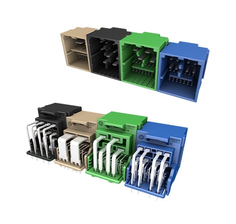
Control Unit Header (CH2) - Mixed Miniaturized Wire-to-Board Connector Solutions
TE's new generation of mixed miniaturized standard wire-to-board connectors have been designed from the outset with the need for flexible layout of domain control connections in mind. It’s compact in structural design and offers a variety of optional interfaces to cover a wide range of current-carrying requirements.
ZONAL
Reduced E/E architecture complexity, space, weight & cost
SPACE
Miniaturized design enabling significant PCB space savings
FLEX
Flexible connector system with broad current coverage across mixed interfaces


MODULAR VS. HYBRID VS. MIXED CONNECTIVITY SOLUTIONS
MIXED |
Mixed connectors are designed to combine multiple Signal and Power terminal sizes within a single connector interface (i.e. 0.50mm, 0.64mm, 1.2mm, 2.8mm, etc.) |
| HYBRID (Signal, Power, and Data) | Hybrid connectors take the concept of mixed connectors further by integrating high-speed Data Connectivity terminals within a single connector. |
| MODULAR (Flexible, Scalable, Automation-Ready & Miniaturized) | Modular connectors can be customized or adapted by combining different modules or components into a single connector housing leading to maximum flexibility, scalability and time-to-market. |
Power Meets Precision: TE Connectivity’s New CH2 Miniaturized Mixed Connectors
As vehicle architecture evolves toward zonal and domain controllers, engineers must integrate more signal and power circuits into increasingly compact electronic control units. This demands connector solutions that maximize PCB space without compromising performance or reliability.
TE Connectivity’s Control Unit Header (CH2) connector platform combines trusted NanoMQS 0.50 mm, MCON 1.2 mm, and AMP MCP 2.8/6.3 mm terminal technologies in a compact, modular wire-to-board system. Its space-efficient, horizontal (90°), stackable header design supports multiple mixed-pin configurations, providing the flexibility to integrate signal and power connectivity while scaling across ECU designs. Ready for next-generation applications, CH2 combines a miniaturized footprint, adaptable modular architecture, and proven terminal technologies to help customers maximize PCB space, simplify development, and deliver the reliability and performance that leading-edge automotive designs demand.
KEY BENEFITS
- Compact, miniaturized design - Maximizes PCB space for high-density electronic control units.
- Smart Design: Horizontal (90°) stackable header design with multiple mixed-pin variants (12P, 23P, 28P, 29P, 52P and 73P).
- Mixed signal & power platform: Combines proven NanoMQS 0.50mm, MCON 1.2mm, and AMP MCP 2.8 & 6.3mm terminals in one connector.
- Scalable connector platform - Stackable headers support flexible pin-count configurations and common PCB designs.
- High-current performance - Supports applications from 6A to 52A across multiple wire sizes.
- Automotive-grade reliability - Designed to meet demanding USCAR and OEM performance requirements.
- Manufacturing ready - Supports Pin-in-Paste assembly and reflow soldering for efficient production.
- Error-proof assembly - Mechanical keying and color coding help prevent mis-mating.
- Future-ready connectivity - Optimized for zonal and domain controller architectures.
Control Unit Header (CH2) - Headers
Part Number
|
Positions
|
Terminals
|
Orientation
|
Coding
|
Soldering
|
Plating
|
12 |
4x 2.8 8x 1.2 |
90° |
4 |
PIP / Wave Soldering |
Tin (Sn) / Silver (Ag) |
|
23 |
2x 6.3 21x 0.50 |
90° |
4 |
PIP / Wave Soldering |
Tin (Sn) / Silver (Ag) |
|
28 |
4x 2.8 24x 0.50 |
90° |
6 |
PIP / Wave Soldering |
Tin (Sn) / Silver (Ag) |
|
29 |
8x 1.2 21x 0.50 |
90° |
4 |
PIP / Wave Soldering |
Tin (Sn) / Silver (Ag) |
|
52 |
23P + 29P |
90° |
2 |
PIP / Wave Soldering |
Tin (Sn) / Silver (Ag) |
|
73 |
35P + 38P |
90° |
1 |
PIP / Wave Soldering |
Tin (Sn) / Silver (Ag) |
 CH2 - 12POS Unsealed Mixed Header Assemblies
 CH2 - 23POS Unsealed Mixed Header Assemblies
 CH2 - 28POS Unsealed Mixed Header Assemblies
 CH2 - 29POS Unsealed Mixed Header Assemblies
 CH2 - 52POS Unsealed Mixed Header Assemblies
 CH2 - 73POS Unsealed Mixed Header Assemblies
This product table can only be viewed on desktop.
Learn more or contact our team today to integrate this solution into your platform.
Control Unit Header (CH2) - Plugs
Part Number
|
Positions
|
Terminals
|
Orientation
|
Coding
|
Soldering
|
Plating
|
12 |
4x 2.8 8x 1.2 |
90° |
4 |
PIP / Wave Soldering |
Tin (Sn) / Silver (Ag) |
|
23 |
2x 6.3 21x 0.50 |
90° |
4 |
PIP / Wave Soldering |
Tin (Sn) / Silver (Ag) |
|
28 |
4x 2.8 24x 0.50 |
90° |
6 |
PIP / Wave Soldering |
Tin (Sn) / Silver (Ag) |
|
29 |
8x 1.2 21x 0.50 |
90° |
4 |
PIP / Wave Soldering |
Tin (Sn) / Silver (Ag) |
|
52 |
23P + 29P |
90° |
2 |
PIP / Wave Soldering |
Tin (Sn) / Silver (Ag) |
|
73 |
35P + 38P |
90° |
1 |
PIP / Wave Soldering |
Tin (Sn) / Silver (Ag) |
 CH2 - 12POS Unsealed Mixed Plug Assemblies
 CH2 - 23POS Unsealed Mixed Plug Assemblies
 CH2 - 28POS Unsealed Mixed Plug Assemblies
 CH2 - 29POS Unsealed Mixed Plug Assemblies
 CH2 - 52POS Unsealed Mixed Plug Assemblies
 CH2 - 73POS Unsealed Mixed Plug Assemblies
This product table can only be viewed on desktop.
Learn more or contact our team today to integrate this solution into your platform.
Control Unit Header Gen 2 (CH2) - Terminals
Terminals
|
Applicable Wire
|
Current Rating
|
Material/Finish
|
0.13-0.22mm2 |
6A |
Copper Alloy / Tin |
|
0.35-1.5mm2 |
17A |
Tin / Silver |
|
0.35-4.0mm2 |
40A |
Tin / Silver |
|
0.5-6.0mm2 |
52A |
Tin / Silver |
 NanoMQS 0.50mm
 MCON 1.2mm
 MCP2.8mm
 MCP6.3mm
This product table can only be viewed on desktop.
Learn more or contact our team today to integrate this solution into your platform.
Control Unit Header (CH2) Applications
| Telematic Control Unit | • Power Supply • I/O Interface |
| Vehicle Body Control Units | • Body Control Module (BCM) • Lighting Module • Door Module • Mirror Module |
| Infotainment | • Power Supply • Display Backlight Power • Button/HMI Interface • Audio Control |
| Body and Comfort Systems | • Seat Control Module • Window Lift Module • HVAC Controller • Sunroof Controller |
| ADAS | • Camera Power Distribution • Radar Power Interface • Sensor Power Module |
Control Unit Header (CH2) Frequently Asked Questions
Q. What is the Control Unit Header (CH2) connector system?
A. The Control Unit Header (CH2) connector system is a compact, miniaturized automotive wire-to-board connectivity platform designed for next-generation zonal and domain control architectures. It combines power and signal connections within a single, space-efficient interface, helping engineers optimize PCB space, simplify connector architectures, and support high-density electronic control units (ECUs).
Q. What problems was CH2 designed to solve?
A. CH2 was designed to address the challenges of next-generation zonal and domain controller architectures, where more signal and power circuits must fit within increasingly compact electronic control units. It helps maximize PCB space by combining multiple proven terminal technologies into a single modular connector system, reducing the number of separate connectors required. CH2 also simplifies design through scalable, stackable configurations that support platform reuse, lower development complexity, and provide the flexibility to adapt to evolving vehicle architectures.
Q. What are the key benefits of CH2 compared with traditional connector systems?
A. The CH2 connector system offers: • Miniaturized packaging for improved PCB space utilization • Signal and power connectivity within one connector interface • Multiple terminal sizes for different current requirements • A flexible, spliceable connector architecture • Mechanical coding options to help prevent mismating • Established TE automotive terminal technologies • Support for efficient PCB assembly processes.
Q. Which automotive applications is CH2 designed for?
A. CH2 is designed for high-density automotive electronic control units (ECUs), including zonal controllers, domain controllers, body control modules, gateway modules, ADAS controllers, cockpit and infotainment systems, and power distribution applications. Its compact, mixed power-and-signal architecture makes it ideal for applications where PCB space, power distribution, and design flexibility are critical.
Q. Which terminal systems, wire sizes, and current ratings are supported?
A. CH2 supports TE Connectivity's proven NanoMQS 0.50, MCON 1.2, MCP 2.8, and MCP 6.3 terminal systems, providing wire size support from 0.13 mm² to 6.0 mm² and current ratings from up to 6 A to 52 A, depending on the selected terminal, wire size, ambient temperature, circuit loading, and application conditions.
| Terminal | Wire Size | Current Rating* |
| NanoMQS 0.50 |
0.13–0.22 mm² |
Up to 6 A |
| MCON 1.2 |
0.35–1.5 mm² |
Up to 17 A |
| MCP 2.8 |
0.35–4.0 mm² |
Up to 40 A |
| MCP 6.3 |
0.5–6.0 mm² |
Up to 52 A |
*Current capability depends on the specific application and operating conditions. Refer to the applicable TE product specifications for detailed performance information.
Q. Which connector configurations are available?
A. The CH2 portfolio offers multiple connector configurations to support a wide range of automotive ECU requirements. Available connector sizes include 12, 23, 28, 29, 52, and 73 positions, with terminal combinations varying by configuration. CH2 currently supports 90° header orientations, providing design flexibility for compact PCB layouts and challenging packaging requirements.
Q. Can CH2 combine signal and power circuits in one connector?
A. Yes. CH2 connectors are designed to combine signal and power circuits within one connector interface. Depending on the selected configuration, the system can combine miniaturized signal terminals with medium-current and high-current power terminals.
Q. How does CH2 optimize PCB space?
A. CH2's miniaturized, platform-optimized design combines multiple terminal sizes and power and signal circuits within a single, compact connector interface. By reducing the number of separate connectors required in an electronic control unit (ECU), CH2 helps maximize PCB space, simplify connector architectures, and enable more compact, high-density module designs.
Q. What is the spliceable connector architecture?
A. The spliceable architecture allows defined connector sections to be combined into larger configurations.
This provides engineers with increased flexibility when selecting the required number and type of signal and power circuits while using standardized connector interfaces.
Q. How does CH2 simplify assembly and prevent mismating?
A. CH2 incorporates mechanical coding and keying features to help prevent incorrect mating and ensure reliable connector installation, even when multiple connectors are located close together within an electronic control unit (ECU). Its streamlined design and low mating force also support faster, more efficient, and error-proof assembly processes.
Q. Which PCB header orientation is available?
A. The current CH2 portfolio includes 90-degree PCB header configurations. Customers should review the individual product drawing to confirm the exact connector dimensions, PCB footprint and installation requirements.
Q. Which PCB assembly processes are supported?
A. Selected CH2 PCB headers are designed to support:
-Pin-in-paste processing
-Reflow soldering
-Wave soldering
The applicable assembly process depends on the selected product configuration. Refer to the individual product drawing and application specification for detailed requirements.
Q. Is CH2 suitable for zonal and domain controller architectures?
A. Yes. The CH2 connector system is designed to support the connectivity requirements of modern domain and zonal vehicle architectures. Its compact design and ability to combine signal and power circuits make it suitable for multifunctional automotive control units.
Q. What makes CH2 different from traditional connector systems?
A. Unlike fixed connector solutions, CH2 is a scalable platform that supports flexible pin combinations, mixed power and signal interfaces, and multiple application requirements while helping reduce variant complexity across vehicle programs.
Q. How can CH2 help reduce system costs?
A. By enabling platform reuse across multiple ECUs, reducing connector variants, simplifying assembly, and providing a competitive alternative to incumbent solutions, CH2 can help lower overall system complexity and cost.
Q. Where can I find technical documentation and product drawings?
A. Available products, drawings, specifications and additional technical information can be found on the CH2 product page at: www.te.com/ch2
Customers should review the individual product documentation before completing the application design.