Industrial Machinery
Hydraulic Pressure Sensors
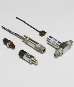
TE Connectivity manufactures pressure sensors, transducers and transmitters for hydraulic pressure measurement applications.
Sensors are a critical component in hydraulic applications, where there can be mechanical construction challenges in external environments. Challenges for designers and system integrators and may result in project delays or field reliability issues if not addressed appropriately.
As pressure transducers are installed in hydraulic systems, various mechanical challenges should be addressed and recognized within the design. Below are the typical areas within hydraulic systems that system designers need to consider as part of the design process.
- Operating pressure
- Pressure spikes
- Proof pressure
- Fluid connections
- Burst pressure
- Vibration and mechanical shock
- Pressure fatigue
- Environmental durability
Each of these concerns are addressed through the sensor design and validation. Over pressure ratings, burst pressure ratings, fatigue analysis, and the use of pressure snubbers are all part of the design process and validated both through simulation and empirical testing.
Environmental Conditions
Standard pressure sensors can be packaged with the electronics sealed from the outside environment. Known as sealed gauge, the pressure sensor is calibrated to the barometric pressure of the date of calibration. This will prevent moisture and dust from entering the pressure sensor for gauge pressure sensors. Because gauge pressure sensors are referenced to the atmosphere, they typically "breathe" through a vent tube in the cable jacket or through a hole in the connector. Sealing the pressure sensor is common for hydraulic uses because the pressure ranges are high enough that the difference in barometric pressure from location-to-location and day-to-day is insignificant as a percentage of the measurement range. The better trade-off is to protect the sensor from humidity, dust, ice, and high pressure wash-down.
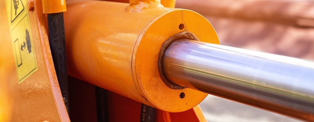
Mechanical Packaging
In this use case, if a fork lift has a full load and drops it onto a concrete floor at full speed, the hydraulic system will see a pressure transient exceeding the limits of the pressure sensor. The restrictor plug dampens the pressure spike and protects the diaphragm of the sensor. The restrictor plug, also referred to as a snubber, is on the inside of the port rather than an added adapter. This can reduce the overall length and weight of sensors that use external restrictor plugs.
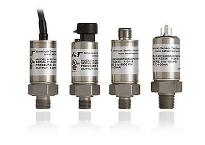
Highlighting this featured series, the AST4000 industrial pressure sensor is available with 1/4" NPT male, 7/16-20 UNF (SAE4) and 9/16-18 UNF (SAE6) process connections. TE can integrate a welded stainless steel restrictor plug inside the pressure port in order to reduce the inside diameter orifice size to protect against pressure transient common to hydraulic systems.
Electrical Packaging
This family of hydraulic pressure sensors offers flexibility in the connection type. With a variety of cable lengths, the customer can connect to their electronics with ease. Depending on the output signal, TE will recommend maximum distances to run the cable to limit signal loss. TE also offers a full line of connectors that are integrated into the housing of the pressure sensor including: DEUTSCH DT04, M12x1, PT06A, and DIN. For OEM requirements, TE can also offer a custom cable assembly with specific cable lengths and integral connectors.
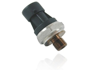
The M7100 features a welded housing, to shield from electrical interference and protect the electronics of the sensor from application environments and tough installations. The electronics of the pressure sensor also have EMI (Electromagnetic Interference) and RFI (Radio Frequency Interference) protection to the latest CE standards for industrial equipment.
Microfused™ Technology
From the outside, pressure transducers all look relatively the same, yet the core sensing element varies greatly among sensor manufacturers. One of the most common economical and technologically feasible approaches is to use a strain gauge as the sensing element to transfer the mechanical strain the pressure induces on a diaphragm into an accurate and repeatable electrical output signal. Our Microfused strain gauge technology is used in a Wheatstone bridge configuration to transform the strain into a voltage output signal.
TE designed the sensing element as a single machined component integrated with the threaded port. This optimized design provides a robust signal from the sensing element and provides great levels of overpressure and burst performance. A glass bonding process is used to fuse the silicon strain gauges to the metal port. The gauges are optimally positioned to properly measure the strain as the pressure changes. Industry proven wire-bonding processes are used to make connections between the gauges and signal conditioning electronics.
Competing technologies in the hydraulic pressure sensor market such as thin-film deposition, thick-film and ceramic- based technologies utilize separate diaphragms with low sensitivity sensing elements. These technologies require additional welds in the fluid paths, internal O-rings, or require additional processing steps that can drive long supply chain lead times. Alternate technologies may require high strains in their sensing element to compensate for low sensitivity. These high strains along with multi-piece construction can result in reduced long term stability and durability.
The Microfused strain gauge technology has been proven in high-volume production, has low risk of supply chain disruption and delivers a robust single-piece fluid connection, reducing the risk of internal sensor failures and other mechanical challenges.