Vision-Guided Robotic Sheet-Metal Cage Assembly
ABSTRACT
High-precision sheet-metal cage assembling is labor intensive. To reduce the assembling cost, and to improve the assembling efficiency and the quality, robotics with its key advantages in speed, precision and flexibility has been an optimal option to be applied to construct the automatic assembling system. Presented herein is the robotics-based technology for Sheet-metal Cage Assembling to demonstrate, verify and optimize the key solutions in automating Mass-customized Assembling Process.
PROBLEM STATEMENT
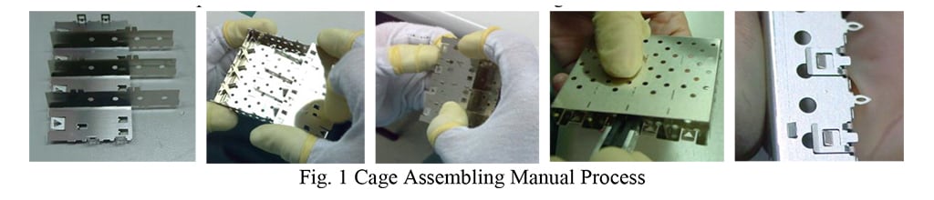
High-precision sheet-metal cage assembling processes are labor intensive, and there are more than 52 operators working intensively on the Process. As shown in Fig. 1, the separators are assembled to the Bottom Cage to form a Sub-assembly, and then the Sub-assembly is assembled with the Kick-out Spring and the Top Cage to assemble the Cage Assembly. Apparently, it is particularly necessary to be very careful for cage assembling, as the product is easy to get deformed and scratched. The thickness of the Sheet-metal part is 0.25 mm, and the assembling precision is less than 0.03 mm. In addition, there are more than 100 product part numbers to be supported, the product illustrated in Fig.1 is a typical SFP+ 1X4 Cage Product, and there are some other products as 1XN and 2XN categorized the product families of SFP, SFP+, QSFP, ZQSFP etc. Obviously, to automate the Cage Assembling Process is to deal with a High Mix and Low Volume Mass Customized Automation Problem, and the conventional automation methods with hard tooling would not be suitable in this case for the requirement of Mass Customized Assembling.
Robotics with its key advantages in speed, precision and flexibility has been regarded as an optimal option to be applied to construct the automatic and flexible assembling system. This research explores the interesting capabilities of the robot/robotics, and presents the solutions for the mass customized sheet metal cage assembling process with Robotics that may generate excellent business impact and technology development to TE. To improve the reliability and the robustness of the Robotic Cage Assembling System, this research also studies the details of assembling process and conducts two Design of Experiments (DoEs) to optimize the Separator & Bottom Cage Assembling and Top Cage & Kick-out Spring Assembling. The Robotics-based Assembling System and the Assembling Process Optimization Method developed from this research could hopefully be applied to other Product Assembling Processes throughout TE Business Units to significantly reduce the Assembling Cost and improve the Assembling Efficiency and Quality as well.
METHODS AND RESULTS
Introduction to Industrial Robot
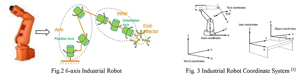
Industrial Robot is normally known as the SCARA Robot, the 6-axis Robot and the Delta Robot. The SCARA Robot is of 3-DOF (Degree of Freedom) Translations and 1-DOF Rotation, and is generally employed to perform pick-and-place operations; the 6-axis Robot is of 3-DOF Translations and 3-DOF Rotations, and is very versatile to be applied in various manufacturing and assembling processes. The Delta Robot is of parallel architecture generally with 3-DOF Translations and 1-DOF Rotation, and it is normally applied to perform fast pick-and-place operations. For the Sheet-metal Cage Assembling Process, the assembling of the Separator and the Top Cage requires both translations and rotations for the part to follow an assembling path to finish assembling, so the 6-axis Robot is preferred to be employed in this case. Fig.2 illustrates the typical 6-axis Robot and the Robot Architecture to study the mobility of the Robot End-effector. The 6-axis Industrial Robot is also known as 6-R Mechanism (R: Revolute Joint), which can in further be decomposed into two parts: the Arm and the Wrist. The Robot Arm enables 3-DOF translations, and the Robot Wrist enables 3-DOF rotations. With the coordination between the Robot Arm and the Robot Wrist, the Robot End-effector is able to reach any defined pose within its workspace, and would be quite agile to fulfill the Sheet-metal Cage Assembling Process.
Industrial Robot has now been well developed with its modelling and control method, as well as with good robot programming language & programming interface. It is not necessary for the end user to look into the details for motor control, direct kinematics/inverse kinematics, or even dynamics. But it is necessary to develop some techniques with the robot programming languages on robot motion and path planning. With the end-effector installed to the robot, the motion and path planning is based on the Robot Tool Coordinate which would be defined and attached to the robot end-effector. Fig. 3 illustrates some concept for the key robot coordinate systems. The precise control of the robot path is to precisely control the critical robot targets. Especially on the Cage Assembling Process, the step to construct the robot assembling path might be linear translation or rotation, or even the combination of the both, in order to construct smooth assembling path to avoid any interference, it is critical to define precisely the robot step size. For each Robot Target, the robot end-effector shall be precisely defined in its position (x, y, z) and orientation (Ex, Ey, Ez), where x, y, z are the coordinates w.r.t. the Object Coordinate System, Ex, Ey, Ez are the Euler-angles w.r.t the Object Coordinate System.
Vision-guided Robotics
For high-precision assembling, the traditional automation method is to design and manufacture high-precision mechanical fixtures to perform positioning for the part, and develop high-precision mechanism to perform part loading and assembling, which would be a challenge to the mechanical system to maintain the precision. While with the vision-guided robotics method, a vision system is integrated as part of the robotic system to precisely identify the pose of the part gripped at the Robot Tool, then the Robot/Robot Tool adaptively translate or rotate the part based on the feedback from vision identification to ensure the assembling precision.
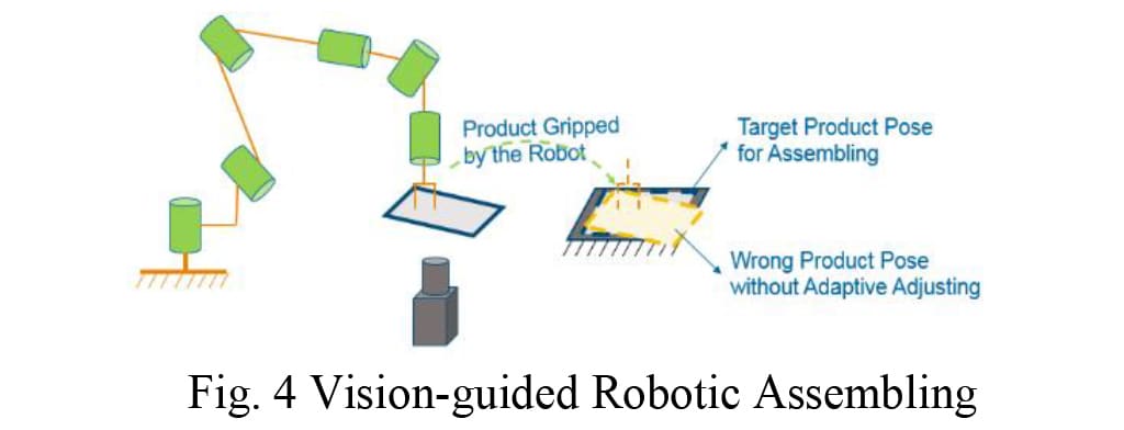
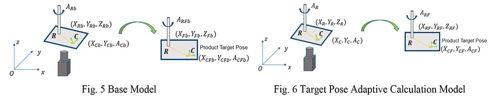
Fig. 4 illustrates a typical vision-guided robotic system for adaptive assembling / pick-and-place operation. As the robot may not pick up the product at the same position or orientation due to some positioning errors, the constant robot pose generated by robot teaching might fail to assemble the product, the vision system would be very helpful to guide the robot to adaptively adjust the assembling path to guarantee the reliability and robustness of the assembling system.
The procedure to develop robot adaptive assembling algorithm is to create the Base Model as reference model first, and then to formulate the Target Pose Calculation Model to adaptively adjust the robot pose to assemble the product precisely. The Base Model is created by taking the Robot Pose for Image Capturing (XRb, YRb, ARb), the identified Product Pose at the Robot Tool (XCb, YCb, ACb) by the 2D Vision System, and the Teach Pose to assemble the Product precisely (XFb, YFb, AFb) as the reference base, with which the Product Target Pose (XCFb, YCFb, ACFb) is calculated and it is obviously that the Product Target Pose is constant for assembling the product precisely. Here, X/Y stands for the position, A stands for the rotation angle along z-axis, as here is using 2D Vision System, the pose component at the 2D Plane is studied here.
As shown in Fig. 4, the Robot Tool grips the Product at Point R, and the feature to represent the Product position and orientation at the Robot Tool is Frame C, with known of the Robot Teach Pose to assemble the product, the Product Target Position for product assembling is calculated based on the planar transformation of vector 𝒗𝑟𝑐 from the image capturing pose to the assembling pose and the Robot Teach Pose to assemble the product. Hence, the Product Target Position is formulated as:

Where, 𝒗𝑟𝑐 = (𝑋𝐶𝑏 − 𝑋𝑅𝑏, 𝑌𝐶𝑏 − 𝑌𝑅𝑏)𝑇.
The Product Target Orientation for product assembling is calculated based on the product feature orientation ACb and the rotational variation of the Robot ∆𝐴𝑏 = 𝐴𝑅𝐹𝑏 − 𝐴𝑅𝑏, as Eq. (2):
𝐴𝐶𝐹𝑏 = 𝐴𝐶𝑏 + ∆𝐴𝑏 (2)
The Adaptive Robot Target Pose for assembling the product is formulated with the model shown in Fig. 6, and it is easy to know the Product Target Pose, as it is the same with the reference base:
𝑋𝐶𝐹 = 𝑋𝐶𝐹𝑏, 𝑌𝐶𝐹 = 𝑌𝐶𝐹𝑏, 𝐴𝐶𝐹 = 𝐴𝐶𝐹𝑏 (3)
The Robot Pose for image capturing is (XR, YR, AR), the identified Product Pose at the Robot Tool is (XC, YC, AC), and the variation in product rotational angle from the image capturing pose to the assembling pose is formulated as Eq. (4):
∆A = 𝐴𝐶𝐹 − 𝐴𝐶 (4)
Therefore, the target robot orientation to assemble the product is adaptively calculated with the identified product feature orientation as Eq. (5):
𝐴𝑅𝐹 = 𝐴𝑅 + ∆𝐴 = 𝐴𝑅 + 𝐴𝐶𝐹 − 𝐴𝐶 (5)
The target robot position for product assembling is formulated based on the planar transformation of the vector 𝒗𝑟𝑐 and the Product Target Pose as Eq. (6):

Where, 𝒗𝑟𝑐 = (𝑋C − 𝑋R, 𝑌C − 𝑌R)T
With the vision system to precisely identify the product feature as shown in Fig.5 and Fig. 6, the robot pose to assemble the product precisely is not a constant pose but an adaptive robot pose formulated by Eq. (5) and Eq. (6).
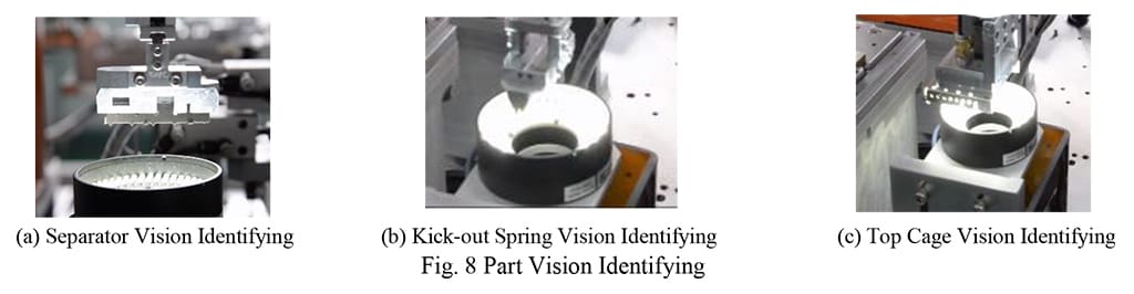
For the Sheet-metal Cage Assembling Process, the mechanical positioning accuracy for the Separator and the Kick-out Spring is around 0.3 mm, and the mechanical positioning accuracy for the Top Cage is around 0.1 mm in position and around 0.25 degrees in orientation. To meet the assembling precision for 0.03 mm, a vision system with positioning accuracy for +/-0.003 mm is integrated to adaptively guide the robot as shown in Fig. 8. Combined with the robot repeatability of +/-0.01 mm, the overall accuracy for the robot system to perform assembling is around 0.02 mm, which is sufficient for fulfilling the Sheet-metal Cage Assembling Process.
Robotic Sheet-metal Cage Assembling System
To develop a Mass Customized Automation System to cover high-precision assembling of High Mix and Low Volume Cage Products, the Sheet-metal Cage Assembling System (see Fig. 7-a) is constructed with a 6-axis Robot to perform part loading and assembling, a Vision System to precisely identify the part pose gripped at the Robot Tool and the Assembling Fixture. The Robot is equipped with two Robot Tools, one is of a Pneumatic Gripper to perform loading and assembling of the Separator and the Kick-out Spring, the other one is of a Pneumatic Sucker to perform loading and assembling of the Bottom Cage and the Top Cage. The Assembling Fixture is transported by a linear screw between the Separator Assembling Station and the Top Cage & Kick-out Spring Assembling Station.
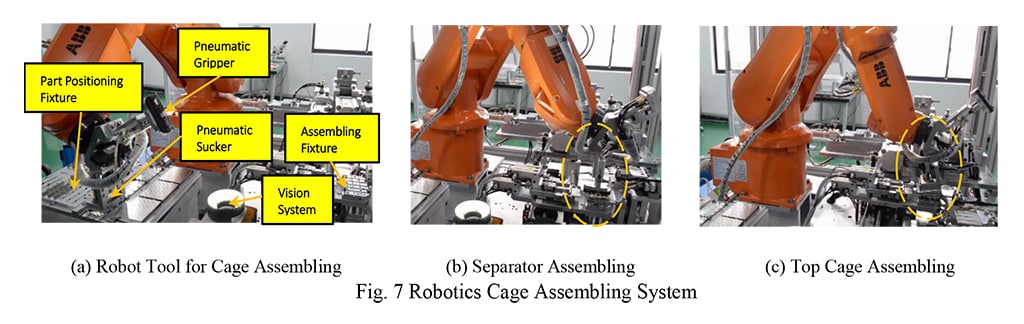
The Robot first loads the Bottom Cage to the Assembling Fixture at the Separator Assembling Station, and then loads and assembles the Separators respectively with the Bottom Cage to make a Sub-assembly, as shown in Fig. 7-b. Then the linear screw transports the Assembling Fixture with the Sub-assembly to the Kick-out Spring & Top Cage Assembling Station, where the Assembling Fixture is precisely positioned and the Separators are held precisely by the Separator Holding Mechanism for Kick-out Spring and Top Cage assembling, as shown in Fig. 7-c. With the vision system to precisely identify the pose of the part gripped at the Robot Tool, the Separator, Kick-out Spring and Top Cage are adaptively assembled with the formulations developed by Eq. (5) and Eq. (6).
Robotic Assembling Process Optimization
In order to improve the reliability and to maximize the capability of the Robotic Sheet-metal Cage Assembling System, two Design of Experiments (DoEs) have been conducted for the optimization of the assembling process, one DoE is for the Separator & Bottom Cage Assembling, the other DoE is for the Kick-out Spring and Top Cage Assembling. The key factors for the high-precision assembling process are generally the Part Positioning Mechanism at the Assembling Fixture and the Robot Assembling Path.
For the Separator & Bottom Cage Assembling Process Optimization, the Bottom Cage is well positioned and fixed by the Positioning Mechanism at the Assembling Fixture. As is verified to be not much issue at the Assembling Fixture for Separator Assembling, two other factors (Assembling Speed and Assembling Path) have been selected for optimizing the yield rate, and the Pareto as shown in Fig. 9-a suggests that the Assembling Path is the Effective Factor that affects greatly the assembling yield rate. An optimal Separator Assembling Yield Rate has been achieved as 97%, with the optimal Separator Assembling Path shown in Fig. 10-a and Fig. 10-b. Due to the differences in Separator Structure, the Assembling Path for Separator #1 is different with the path of Separator #2 and #3 to avoid any interference with the Bottom Cage.
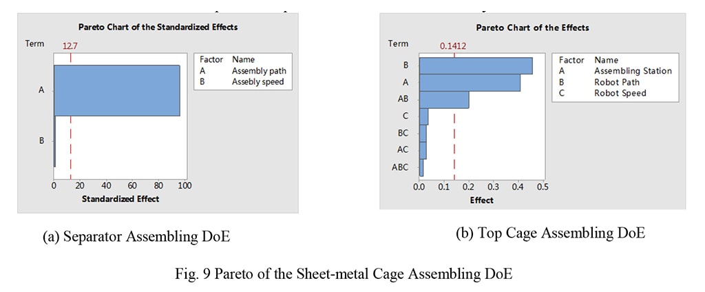
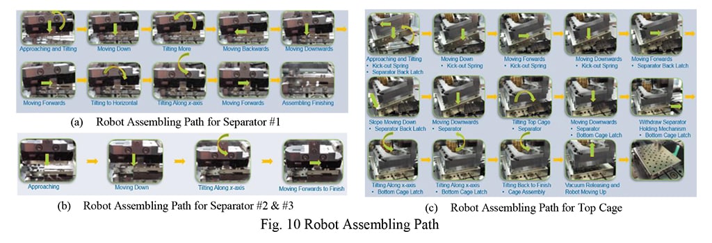
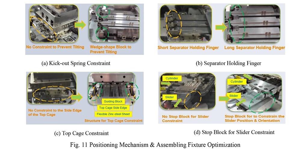
For the Top Cage Assembling Optimization, three factors have been selected to conduct the assembling DoE, and the Pareto as shown in Fig. 9-b illustrates that the Robot Path, Assembling Fixture & Positioning Mechanism and the Interaction of the two factors are the Effective Factors. An optimal Top Cage Assembling Yield Rate has been achieved as 97%, with the optimal Top Cage Assembling Path as shown in Fig. 10-c, and the optimal Positioning Mechanism & Assembling Fixture as shown in Fig. 11. As the Top Cage has to be well fit with the Kick-out Spring, the Separator and the Bottom Cage to be assembled successfully, each of optimal the assembling step is well designed to take into consideration of the critical items. For the Positioning Mechanism & Assembling Fixture Optimization to coordinate with the Robot Assembling Path to improve the Assembling Yield Rate, the Kick-out Spring Constraint has been improved to be constrained by a pair of Wedge-shape blocks to avoid the spring being tilted by any slight force acted by the Top Cage, which might result in Top Cage Assembling NG, as shown in Fig. 11-a. The Separator Holding Finger has been improved to longer fingers to hold the Separators tightly and precisely to avoid any vibration in the Separator with high speed, as shown in Fig. 11-b. The Top Cage Constraint has been improved with constraining the Side Edges with the Guiding Block and the Flexible Zinc-steel Sheet to ensure compatibility of the large tolerance (-0.1~0.7 mm) of the distance between the two Side Edges of the Top Cage, as shown in Fig. 11-c. Considering the clearances between the Slider and its Guiding Track for feeding and withdraw the Separator Holding Finger, with the pneumatic cylinder to press at the Separator Holding Fingers to hold the Separator tightly, there may be some positional and rotational errors for the Separators and the Bottom Cage, a Stop Block is added to constrain the Slider Position and Orientation to guarantee the positioning accuracy of the Separator and Bottom Cage at the Assembling Station, which is critical for the assembling reliability and robustness, as shown in Fig. 11-d.
Without loss of the Assembling Yield Rate, the Assembling Efficiency has also been improved by optimizing the robot speed. Tab. 1 shows the optimal cycle time for assembling each part, where the Robot Travel Speed is optimized to 2000 mm/s, the Robot Speed for Separator and Kick-our Spring Assembling is optimized to 50 mm/s, and the Robot Speed for Top Cage Assembling is optimized to 30 mm/s. The Optimal Cycle Time meets the requirement for industrialization of the cage assembling process.
Table 1
| Assembling Item | Bottom Cage | Separator #1 | Separator #2 | Separator #3 | Kick-out Spring | Top Cage |
| Cycle Time (s/pcs) | 2.2 | 4.6 | 3.2 | 3.4 | 4.0 | 7.0 |
DISCUSSION AND KEY POINTS
Production Machine Development for Sheet-metal Cage Assembling
This research conducts feasibility verification of the Robotics-based Sheet-metal Cage Assembling, and carried out two DoEs on assembling process optimization to improve the Assembling Yield Rate and the Assembling Cycle Time. Obviously, the technology has been verified to meet the target for industrialization, and the DoE Platform has been transferred to D&D Zhuhai Plant to serve in mass production, the latest production data shows the platform is performing at a yield rate for 98%, with labor cost saving for 4 operators ($48000 cost saving yearly). The next step is construct the Production Machine for Sheet-metal Cage Assembling, and it is predicable that the implementation of the production machine with this technology would result in labor cost saving for $520 K yearly for TE D&D Business Unit. Besides, the Robotics-based Sheet-metal Cage Assembling Technology developed here would significantly improve TE’s capabilities in Mass Customized Assembling at a high-precision level, and it is transformable to support the development of Mass Customized Assembling Automation for other Business Units as Automotive, Industrial, CPD, Sensor etc., which would definitely generate great business impacts throughout TE.
ACKNOWLEDGEMENTS
It’s been an exciting journey to work on the development of the Robotics-based Sheet-metal Cage Assembling Technology, the authors are very grateful to the support and sponsorship of the leaders from TE Global Operations and D&D Business Unit, particularly to Philip Gilchrist, Darel Callis, Rolando Saavedra and Marshall Chen for the helpful suggestions and instructions.
REFERENCES
[1] Technical reference manual – RAPID Instructions, Functions and Data types, ABB Robot documentation M2004, rev H, RW5.15
Vision-Guided Robotic Sheet-Metal Cage Assembly
ABSTRACT
High-precision sheet-metal cage assembling is labor intensive. To reduce the assembling cost, and to improve the assembling efficiency and the quality, robotics with its key advantages in speed, precision and flexibility has been an optimal option to be applied to construct the automatic assembling system. Presented herein is the robotics-based technology for Sheet-metal Cage Assembling to demonstrate, verify and optimize the key solutions in automating Mass-customized Assembling Process.
PROBLEM STATEMENT
High-precision sheet-metal cage assembling processes are labor intensive, and there are more than 52 operators working intensively on the Process. As shown in Fig. 1, the separators are assembled to the Bottom Cage to form a Sub-assembly, and then the Sub-assembly is assembled with the Kick-out Spring and the Top Cage to assemble the Cage Assembly. Apparently, it is particularly necessary to be very careful for cage assembling, as the product is easy to get deformed and scratched. The thickness of the Sheet-metal part is 0.25 mm, and the assembling precision is less than 0.03 mm. In addition, there are more than 100 product part numbers to be supported, the product illustrated in Fig.1 is a typical SFP+ 1X4 Cage Product, and there are some other products as 1XN and 2XN categorized the product families of SFP, SFP+, QSFP, ZQSFP etc. Obviously, to automate the Cage Assembling Process is to deal with a High Mix and Low Volume Mass Customized Automation Problem, and the conventional automation methods with hard tooling would not be suitable in this case for the requirement of Mass Customized Assembling.
Robotics with its key advantages in speed, precision and flexibility has been regarded as an optimal option to be applied to construct the automatic and flexible assembling system. This research explores the interesting capabilities of the robot/robotics, and presents the solutions for the mass customized sheet metal cage assembling process with Robotics that may generate excellent business impact and technology development to TE. To improve the reliability and the robustness of the Robotic Cage Assembling System, this research also studies the details of assembling process and conducts two Design of Experiments (DoEs) to optimize the Separator & Bottom Cage Assembling and Top Cage & Kick-out Spring Assembling. The Robotics-based Assembling System and the Assembling Process Optimization Method developed from this research could hopefully be applied to other Product Assembling Processes throughout TE Business Units to significantly reduce the Assembling Cost and improve the Assembling Efficiency and Quality as well.
METHODS AND RESULTS
Introduction to Industrial Robot
Industrial Robot is normally known as the SCARA Robot, the 6-axis Robot and the Delta Robot. The SCARA Robot is of 3-DOF (Degree of Freedom) Translations and 1-DOF Rotation, and is generally employed to perform pick-and-place operations; the 6-axis Robot is of 3-DOF Translations and 3-DOF Rotations, and is very versatile to be applied in various manufacturing and assembling processes. The Delta Robot is of parallel architecture generally with 3-DOF Translations and 1-DOF Rotation, and it is normally applied to perform fast pick-and-place operations. For the Sheet-metal Cage Assembling Process, the assembling of the Separator and the Top Cage requires both translations and rotations for the part to follow an assembling path to finish assembling, so the 6-axis Robot is preferred to be employed in this case. Fig.2 illustrates the typical 6-axis Robot and the Robot Architecture to study the mobility of the Robot End-effector. The 6-axis Industrial Robot is also known as 6-R Mechanism (R: Revolute Joint), which can in further be decomposed into two parts: the Arm and the Wrist. The Robot Arm enables 3-DOF translations, and the Robot Wrist enables 3-DOF rotations. With the coordination between the Robot Arm and the Robot Wrist, the Robot End-effector is able to reach any defined pose within its workspace, and would be quite agile to fulfill the Sheet-metal Cage Assembling Process.
Industrial Robot has now been well developed with its modelling and control method, as well as with good robot programming language & programming interface. It is not necessary for the end user to look into the details for motor control, direct kinematics/inverse kinematics, or even dynamics. But it is necessary to develop some techniques with the robot programming languages on robot motion and path planning. With the end-effector installed to the robot, the motion and path planning is based on the Robot Tool Coordinate which would be defined and attached to the robot end-effector. Fig. 3 illustrates some concept for the key robot coordinate systems. The precise control of the robot path is to precisely control the critical robot targets. Especially on the Cage Assembling Process, the step to construct the robot assembling path might be linear translation or rotation, or even the combination of the both, in order to construct smooth assembling path to avoid any interference, it is critical to define precisely the robot step size. For each Robot Target, the robot end-effector shall be precisely defined in its position (x, y, z) and orientation (Ex, Ey, Ez), where x, y, z are the coordinates w.r.t. the Object Coordinate System, Ex, Ey, Ez are the Euler-angles w.r.t the Object Coordinate System.
Vision-guided Robotics
For high-precision assembling, the traditional automation method is to design and manufacture high-precision mechanical fixtures to perform positioning for the part, and develop high-precision mechanism to perform part loading and assembling, which would be a challenge to the mechanical system to maintain the precision. While with the vision-guided robotics method, a vision system is integrated as part of the robotic system to precisely identify the pose of the part gripped at the Robot Tool, then the Robot/Robot Tool adaptively translate or rotate the part based on the feedback from vision identification to ensure the assembling precision.
Fig. 4 illustrates a typical vision-guided robotic system for adaptive assembling / pick-and-place operation. As the robot may not pick up the product at the same position or orientation due to some positioning errors, the constant robot pose generated by robot teaching might fail to assemble the product, the vision system would be very helpful to guide the robot to adaptively adjust the assembling path to guarantee the reliability and robustness of the assembling system.
The procedure to develop robot adaptive assembling algorithm is to create the Base Model as reference model first, and then to formulate the Target Pose Calculation Model to adaptively adjust the robot pose to assemble the product precisely. The Base Model is created by taking the Robot Pose for Image Capturing (XRb, YRb, ARb), the identified Product Pose at the Robot Tool (XCb, YCb, ACb) by the 2D Vision System, and the Teach Pose to assemble the Product precisely (XFb, YFb, AFb) as the reference base, with which the Product Target Pose (XCFb, YCFb, ACFb) is calculated and it is obviously that the Product Target Pose is constant for assembling the product precisely. Here, X/Y stands for the position, A stands for the rotation angle along z-axis, as here is using 2D Vision System, the pose component at the 2D Plane is studied here.
As shown in Fig. 4, the Robot Tool grips the Product at Point R, and the feature to represent the Product position and orientation at the Robot Tool is Frame C, with known of the Robot Teach Pose to assemble the product, the Product Target Position for product assembling is calculated based on the planar transformation of vector 𝒗𝑟𝑐 from the image capturing pose to the assembling pose and the Robot Teach Pose to assemble the product. Hence, the Product Target Position is formulated as:
Where, 𝒗𝑟𝑐 = (𝑋𝐶𝑏 − 𝑋𝑅𝑏, 𝑌𝐶𝑏 − 𝑌𝑅𝑏)𝑇.
The Product Target Orientation for product assembling is calculated based on the product feature orientation ACb and the rotational variation of the Robot ∆𝐴𝑏 = 𝐴𝑅𝐹𝑏 − 𝐴𝑅𝑏, as Eq. (2):
𝐴𝐶𝐹𝑏 = 𝐴𝐶𝑏 + ∆𝐴𝑏 (2)
The Adaptive Robot Target Pose for assembling the product is formulated with the model shown in Fig. 6, and it is easy to know the Product Target Pose, as it is the same with the reference base:
𝑋𝐶𝐹 = 𝑋𝐶𝐹𝑏, 𝑌𝐶𝐹 = 𝑌𝐶𝐹𝑏, 𝐴𝐶𝐹 = 𝐴𝐶𝐹𝑏 (3)
The Robot Pose for image capturing is (XR, YR, AR), the identified Product Pose at the Robot Tool is (XC, YC, AC), and the variation in product rotational angle from the image capturing pose to the assembling pose is formulated as Eq. (4):
∆A = 𝐴𝐶𝐹 − 𝐴𝐶 (4)
Therefore, the target robot orientation to assemble the product is adaptively calculated with the identified product feature orientation as Eq. (5):
𝐴𝑅𝐹 = 𝐴𝑅 + ∆𝐴 = 𝐴𝑅 + 𝐴𝐶𝐹 − 𝐴𝐶 (5)
The target robot position for product assembling is formulated based on the planar transformation of the vector 𝒗𝑟𝑐 and the Product Target Pose as Eq. (6):
Where, 𝒗𝑟𝑐 = (𝑋C − 𝑋R, 𝑌C − 𝑌R)T
With the vision system to precisely identify the product feature as shown in Fig.5 and Fig. 6, the robot pose to assemble the product precisely is not a constant pose but an adaptive robot pose formulated by Eq. (5) and Eq. (6).
For the Sheet-metal Cage Assembling Process, the mechanical positioning accuracy for the Separator and the Kick-out Spring is around 0.3 mm, and the mechanical positioning accuracy for the Top Cage is around 0.1 mm in position and around 0.25 degrees in orientation. To meet the assembling precision for 0.03 mm, a vision system with positioning accuracy for +/-0.003 mm is integrated to adaptively guide the robot as shown in Fig. 8. Combined with the robot repeatability of +/-0.01 mm, the overall accuracy for the robot system to perform assembling is around 0.02 mm, which is sufficient for fulfilling the Sheet-metal Cage Assembling Process.
Robotic Sheet-metal Cage Assembling System
To develop a Mass Customized Automation System to cover high-precision assembling of High Mix and Low Volume Cage Products, the Sheet-metal Cage Assembling System (see Fig. 7-a) is constructed with a 6-axis Robot to perform part loading and assembling, a Vision System to precisely identify the part pose gripped at the Robot Tool and the Assembling Fixture. The Robot is equipped with two Robot Tools, one is of a Pneumatic Gripper to perform loading and assembling of the Separator and the Kick-out Spring, the other one is of a Pneumatic Sucker to perform loading and assembling of the Bottom Cage and the Top Cage. The Assembling Fixture is transported by a linear screw between the Separator Assembling Station and the Top Cage & Kick-out Spring Assembling Station.
The Robot first loads the Bottom Cage to the Assembling Fixture at the Separator Assembling Station, and then loads and assembles the Separators respectively with the Bottom Cage to make a Sub-assembly, as shown in Fig. 7-b. Then the linear screw transports the Assembling Fixture with the Sub-assembly to the Kick-out Spring & Top Cage Assembling Station, where the Assembling Fixture is precisely positioned and the Separators are held precisely by the Separator Holding Mechanism for Kick-out Spring and Top Cage assembling, as shown in Fig. 7-c. With the vision system to precisely identify the pose of the part gripped at the Robot Tool, the Separator, Kick-out Spring and Top Cage are adaptively assembled with the formulations developed by Eq. (5) and Eq. (6).
Robotic Assembling Process Optimization
In order to improve the reliability and to maximize the capability of the Robotic Sheet-metal Cage Assembling System, two Design of Experiments (DoEs) have been conducted for the optimization of the assembling process, one DoE is for the Separator & Bottom Cage Assembling, the other DoE is for the Kick-out Spring and Top Cage Assembling. The key factors for the high-precision assembling process are generally the Part Positioning Mechanism at the Assembling Fixture and the Robot Assembling Path.
For the Separator & Bottom Cage Assembling Process Optimization, the Bottom Cage is well positioned and fixed by the Positioning Mechanism at the Assembling Fixture. As is verified to be not much issue at the Assembling Fixture for Separator Assembling, two other factors (Assembling Speed and Assembling Path) have been selected for optimizing the yield rate, and the Pareto as shown in Fig. 9-a suggests that the Assembling Path is the Effective Factor that affects greatly the assembling yield rate. An optimal Separator Assembling Yield Rate has been achieved as 97%, with the optimal Separator Assembling Path shown in Fig. 10-a and Fig. 10-b. Due to the differences in Separator Structure, the Assembling Path for Separator #1 is different with the path of Separator #2 and #3 to avoid any interference with the Bottom Cage.
For the Top Cage Assembling Optimization, three factors have been selected to conduct the assembling DoE, and the Pareto as shown in Fig. 9-b illustrates that the Robot Path, Assembling Fixture & Positioning Mechanism and the Interaction of the two factors are the Effective Factors. An optimal Top Cage Assembling Yield Rate has been achieved as 97%, with the optimal Top Cage Assembling Path as shown in Fig. 10-c, and the optimal Positioning Mechanism & Assembling Fixture as shown in Fig. 11. As the Top Cage has to be well fit with the Kick-out Spring, the Separator and the Bottom Cage to be assembled successfully, each of optimal the assembling step is well designed to take into consideration of the critical items. For the Positioning Mechanism & Assembling Fixture Optimization to coordinate with the Robot Assembling Path to improve the Assembling Yield Rate, the Kick-out Spring Constraint has been improved to be constrained by a pair of Wedge-shape blocks to avoid the spring being tilted by any slight force acted by the Top Cage, which might result in Top Cage Assembling NG, as shown in Fig. 11-a. The Separator Holding Finger has been improved to longer fingers to hold the Separators tightly and precisely to avoid any vibration in the Separator with high speed, as shown in Fig. 11-b. The Top Cage Constraint has been improved with constraining the Side Edges with the Guiding Block and the Flexible Zinc-steel Sheet to ensure compatibility of the large tolerance (-0.1~0.7 mm) of the distance between the two Side Edges of the Top Cage, as shown in Fig. 11-c. Considering the clearances between the Slider and its Guiding Track for feeding and withdraw the Separator Holding Finger, with the pneumatic cylinder to press at the Separator Holding Fingers to hold the Separator tightly, there may be some positional and rotational errors for the Separators and the Bottom Cage, a Stop Block is added to constrain the Slider Position and Orientation to guarantee the positioning accuracy of the Separator and Bottom Cage at the Assembling Station, which is critical for the assembling reliability and robustness, as shown in Fig. 11-d.
Without loss of the Assembling Yield Rate, the Assembling Efficiency has also been improved by optimizing the robot speed. Tab. 1 shows the optimal cycle time for assembling each part, where the Robot Travel Speed is optimized to 2000 mm/s, the Robot Speed for Separator and Kick-our Spring Assembling is optimized to 50 mm/s, and the Robot Speed for Top Cage Assembling is optimized to 30 mm/s. The Optimal Cycle Time meets the requirement for industrialization of the cage assembling process.
Table 1
| Assembling Item | Bottom Cage | Separator #1 | Separator #2 | Separator #3 | Kick-out Spring | Top Cage |
| Cycle Time (s/pcs) | 2.2 | 4.6 | 3.2 | 3.4 | 4.0 | 7.0 |
DISCUSSION AND KEY POINTS
Production Machine Development for Sheet-metal Cage Assembling
This research conducts feasibility verification of the Robotics-based Sheet-metal Cage Assembling, and carried out two DoEs on assembling process optimization to improve the Assembling Yield Rate and the Assembling Cycle Time. Obviously, the technology has been verified to meet the target for industrialization, and the DoE Platform has been transferred to D&D Zhuhai Plant to serve in mass production, the latest production data shows the platform is performing at a yield rate for 98%, with labor cost saving for 4 operators ($48000 cost saving yearly). The next step is construct the Production Machine for Sheet-metal Cage Assembling, and it is predicable that the implementation of the production machine with this technology would result in labor cost saving for $520 K yearly for TE D&D Business Unit. Besides, the Robotics-based Sheet-metal Cage Assembling Technology developed here would significantly improve TE’s capabilities in Mass Customized Assembling at a high-precision level, and it is transformable to support the development of Mass Customized Assembling Automation for other Business Units as Automotive, Industrial, CPD, Sensor etc., which would definitely generate great business impacts throughout TE.
ACKNOWLEDGEMENTS
It’s been an exciting journey to work on the development of the Robotics-based Sheet-metal Cage Assembling Technology, the authors are very grateful to the support and sponsorship of the leaders from TE Global Operations and D&D Business Unit, particularly to Philip Gilchrist, Darel Callis, Rolando Saavedra and Marshall Chen for the helpful suggestions and instructions.
REFERENCES
[1] Technical reference manual – RAPID Instructions, Functions and Data types, ABB Robot documentation M2004, rev H, RW5.15