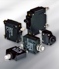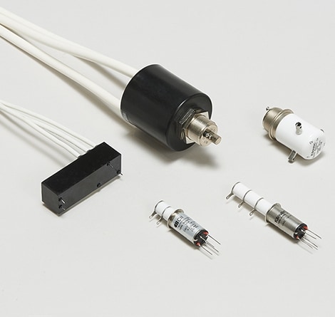
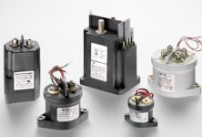
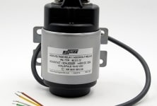
HV Relays: Hermetically sealed for harsh environments
High voltage relays are electromechanical devices whose purpose is to switch to high voltage signals (> 1kV) and high frequency applications. These relays are heavily insulated and are made of strong materials to increase contact life. High voltage relays are used in many technical devices that require voltages that go up to 10,000 V and currents up to 30 A. Unlike conventional relays, high voltage relay coils are located outside the vacuum and further away from the contacts.
Featured Datasheets
High-Voltage Relays (English)
High voltage relays offer low and stable contact resistance over the part life cycle. This type of relay provides an extremely good size-to-power ratio performance, offering voltage ratings up to 70 kVDC and current ratings to 1,000 amps. These overload relays are engineered to interrupt DC loads while providing high shock and vibration resistance and the capacity to withstand a wide range of extreme temperatures. While operating with the same principles as electromechanical relays, these have features that support use in high voltage applications. The contacts are usually contained in a vacuum enclosed by glass or ceramic. This prevents contacts from arching. Aspects to consider are high relay performance specifications, including maximum voltage and dielectric strength. High voltage relays can be mounted in a variety of ways, including: bracket (or flange), DIN rail, panel mount, PCB, and socket.
See High Voltage Relays by Brand and Function
 e
e
 e
e
 e
e
This application note deals with problems related to the methods used in deenergizing electromagnetic relay coils, particularly when a solid state switch is used, and how they affect relay life. It is primarily concerned with the deenergization cycle of the relay, and discusses: 1) The armature and switching dynamics of the relay system upon coil deenergization. 2) How coil induced voltages occur. 3) Techniques for protecting the solid state switch. 4) The adverse effect of a simple coil suppression diode on relay switching dynamics and contact life. 5) The typical “sticking” between mating contacts and the reduced ability to break when using diode suppression. 6) How the addition of a Zener diode to the ordinary diode can provide both voltage suppression and reliable switching performance. Relay deenergization or “drop-out” in typical clapper-type relays normally develops as follows: As the coil supply is interrupted, the magnetic flux decays to the point where the decreasing magnetic holding force (trying to keep the armature seated) drops below the spring forces (trying to unseat it), and armature opening commences. As armature opening continues, spring forces reduces according to the armature position; the countering magnetic force, however, reduces both with armature position and with decay of coil current (both of which reduce coil magnetic flux). As the electrical current in a relay coil is interrupted, an induced voltage transient of the order of hundreds or even thousands of volts may be generated across that coil as its magnetic flux, which is linked by the coil turns, collapses. This induced voltage, plus the coil supply voltage appears across the coil interrupting switch in a simple series switching circuit