-
Product Listing
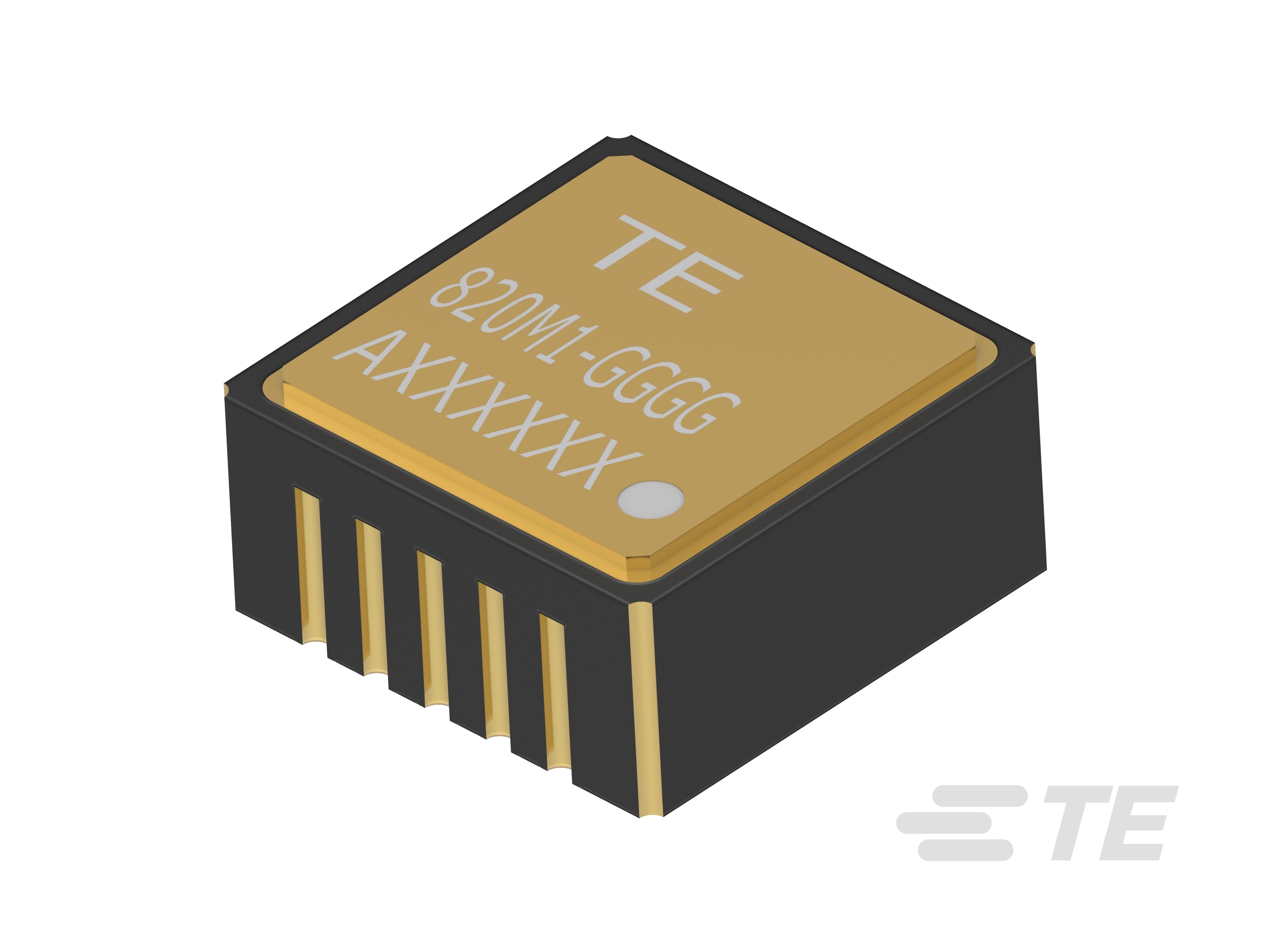
820M1 Single Axis SMT Accelerometers
- MEAS
- 820M1
Product Features
-
Accelerometer Type : 3-Wire Voltage
-
Vibration Sensor Product Type : Piezoelectric Accelerometer
-
Number of Sensing Axes : Uniaxial
-
Frequency Response (Hz): 2 to 10000
-
Full Scale Output Voltage (VDC): ±1.25


Piezoelectric (PE) accelerometer available in ranges from ±25g to ±500g and features a flat frequency response up to >10kHz. The model 820M1 accelerometer feature a stable piezo-ceramic crystal in shear mode with low power electronics, sealed in a fully hermetic LCC package. The PE technology incorporated in the 820M1 accelerometer has a proven track record for offering the reliable and long-term stable output required for condition monitoring applications. The accelerometer is designed and qualified for machine health monitoring and has superior resolution, dynamic range and bandwidth to MEMS devices.
Applications
- Condition monitoring
- Preventive maintenance installations
- Embedded vibration monitoring
- Impact & shock monitoring
- Data loggers
- Bearing installations
- Physical security
Benefits
- Amplified ±1.25V signal output
- 2.8 to 5.5VDC excitation voltage
- 30kHz resonant frequency
- Hermetically sealed LLC package for harsh environments
- Piezo-ceramic shear design
- -40°C to +125°C operating range
- ±25g to ±500g dynamic ranges
- Wide bandwidth to 10,000Hz
- Superior resolution to MEMS devices
- Circuit board mountable, reflow solderable
- Low cost, superior value
Learn More
White Papers
While condition monitoring has been around for years, it is evolving with the Internet of Things (IoT). Watch this webinar to learn how the IoT is evolving, how condition monitoring sensors are enabling this shift, and the value of recognizing sensors as key components of condition monitoring applications.


Frequently Asked Questions
Please also reference the Operating Manual and Datasheet for more information.
Question: The datasheet shows the operating temperature from -40°C to +125°C. The lower limit of -40°C is not low enough; we need to measure down to -55°C. What is your recommendation for meeting this requirement?
Answer: We tested the bias at -55°C. Test result of 832-0500 DC bias change with temperature is shown below, DC Bias changes about 0.5% at -55ºC compared to 25ºC:
25ºC -55ºC
X 1.7423 V 1.7535 V
Y 1.7412 V 1.7477 V
Z 1.7928 V 1.8035 V
Total current supply is 4.1uA at -55ºC which is still within specification. However, for continuous usage down to temperature of -55°C, the model 832M1 and 834M1 are recommended.
Question: Do you happen to have any more detail for the assembling the model 832 and 834 to a board? Our board assembly department is a little concerned about manually soldering this part. It says on your data sheet that the accelerometer can’t go through solder reflow at high temperature and that manual soldering is recommended. I was hoping for some more clarification on this statement.
Answer: The reason for the caution is the potential risk of sensitivity shift in the output after reflow soldering. The units will survive the reflow soldering process. We caution against this process since we have seen a 1-2% sensitivity drop after reflow soldering. For our reflow profile we have a peak temperature of +250°C since we use non-leaded solder for RoHS compliance. A lower reflow profile may result in negligible sensitivity shift. If you can use leaded solder such Sn63 or Sn62 (183°C and 179°C eutectic respectively) then the peak reflow temp should not have to exceed +210°C (60sec max). This should then allow reflow soldering.
Question: We generally conformal coat our circuit boards to protect the circuitry, would there be any concern with conformal coating?
Answer: There are no concerns with conformal coating. The seismic mass system and electronics are all hermetically sealed under the cover.
Question: Can we bake the circuit boards after conformal coating (810M1, 820M1, 832M1, 834M1)?
Answer: Yes. There will be no problem with an over-night bake at +200°F on the model 832M1. We bake the units for 24hours at +250°F during manufacture.
Question: Just a clarification, at 0g output, is the accelerometer output Supply Voltage/2? So that when we have a negative acceleration we approach 0 but not negative?
Answer: Correct. The output will swing nominally ±1.25V about the bias voltage. For a ±100g range accelerometer with 3.3V excitation (bias at 1.65V), the output would be nominally be 0.4V to 2.9V.
Question: If I use structural epoxy around the perimeter to reinforce the vibration sensor onto the circuit board (after soldering) will this affect the vibration response of the sensor? Is there a reinforcement technique you would recommend?
Answer: No, this will not affect the response of the sensor and in fact it is recommended to reinforce the sensor attachment after soldering. Typically we recommend the customer use a low viscosity cyanoacrylate adhesive (such as Loctite 4501) and allow the epoxy to wick underneath accelerometer to fill the gap to the circuit board.
Question: What mounting techniques and materials are recommended to achieve the best high frequency response for the board mountable accelerometers?
Answer: To achieve the best frequency response, we recommend mounting the accelerometer directly to the structure to be measured. An adhesive can be used to secure the accelerometer. Take precautions not to short the output pads underneath the circuit board. Good frequency response can also be achieved by mounting the accelerometer onto a ceramic or hybrid circuit board. FR4 boards should be avoided for applications requiring wide bandwidth measurements since the FR4 material can impart a resonance to your measuring system. If attaching wires to the output pads then these need to be properly secured/anchored at regular intervals to minimize cable motion that can add noise and resonances to the output signal.
The number of questions one can ask about accelerometers is endless. However, the key factors to consider when choosing an embedded PE accelerometer are indicated below.
Performance Requirement Considerations
What is the measurement range (g) for the application? Include a minimum 30% safety margin.
What is the frequency response (bandwidth)? Verify the maximum rotating speed of equipment measurement installation.
What is the measurement resolution required? For slow rotating equipment, a higher sensitivity output should be considered for better resolution.
Over what temperature range should be accelerometer perform with accuracy? The output of the accelerometers will vary marginally over temperature. Consideration should be given to selection if a wide operating temperature range is expected for the installation.
Electrical Requirement Considerations
What type of power supply is available to power the accelerometers? The embedded PE accelerometers are offered in either 3-wire voltage mode that typically require 3.3 to 5.5Vdc excitation or in IEPE 2-10mA current excitation versions.
How will the signal be transmitted from the sensor? Interface circuit should be close to the accelerometers to minimize potential noise coupling issues.
What signal output is needed? The 3-wire voltage mode units have an output of either ±1.25V or ±2.0V depending on model chosen. The IEPE model units have an output of ±5.0V
What models should be considered for long term battery operation? The model 832 and 834 accelerometers are designed for long term battery operation by having a minimal current draw of 4µA.
Physical and Envelope Considerations
How light/heavy can the sensor be? If the sensor is to be mounted on a circuit board, then it is recommended that the unit be mounted at a rigid location on the board, not at a location where it is not supported firmly.
What are the envelope/size constraints? The single axis model 805, 810M1 and 820M1 units are the smallest available but if multiple axis measurements are needed then the model 832M1 and 834M1 series should be considered if there are space constraints.
What mounting technique is required? If reflow soldering, then careful consideration should be taken for the solder reflow profile. Consult the appropriate operating manual.
Please review product documents or contact us for the latest agency approval information.
Product Type Features
-
Sensor Package Embedded
-
Accelerometer Type 3-Wire Voltage
-
Vibration Sensor Product Type Piezoelectric Accelerometer
Electrical Characteristics
-
Excitation Voltage Range (VDC) 2.8 – 5.5
-
Full Scale Output Voltage (VDC) ±1.25
Signal Characteristics
-
Frequency Response (Hz) 2 to 10000
Body Features
-
Primary Product Material Ceramic
-
Product Weight 1 g [ .04 oz ]
-
Number of Sensing Axes Uniaxial
Mechanical Attachment
-
Sensor Mount Type Solder
Usage Conditions
-
Operating Temperature Range -40 – 125 °C [ -40 – 257 °F ]
Operation/Application
-
Output Current Type AC
Industry Standards
-
IP Rating IP68
Other
-
Non-Linearity (FSO) (%) ±1
-
Sensitivity Range (mV/g) .21 | 2.5 | 6.3 | 12.5 | 25 | 50
-
Overall Acceleration Range (±) (g) 25 | 50 | 100 | 200 | 500 | 6000
-
Acceleration Range (±) (g) 25 | 50 | 100 | 200 | 500 | 6000
-
Sensitivity (mV/g) .21 | 2.5 | 6.3 | 12.5 | 25 | 50
CAD Files
- 3D PDF 3D
- Customer View Model English
- Customer View Model English
- Customer View Model English
Datasheets & Catalog Pages
- MODEL 820M1 ACCELEROMETER English