


Connected Vehicles
Discover our portfolio enabling your Data Connectivity to go further.
Discover our Portfolio


On-Demand Webinars


Make Every Connection Count
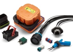
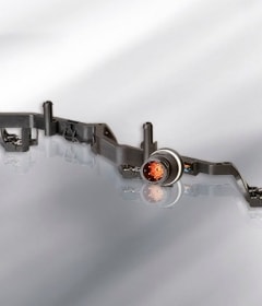
When every connection counts, TE manufactures reliable connectivity products designed to withstand harsh environmental conditions for commercial and industrial transportation.