Trend Insight
Optimizing Signal Integrity while Minimizing Noise
As commercial aircraft handles more data for flight operations, in-flight electronics must also deliver greater levels of passenger connectivity. By: Michael Coon, Industry Specialist in Aerospace Engineering
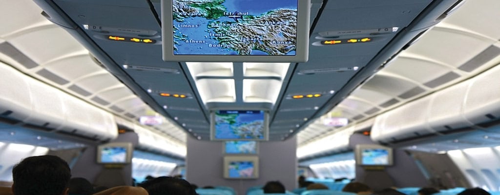
With renewed interest in how and when air travelers can use personal electronic devices (PEDs), EMI control deserves a new look. In-flight entertainment systems are more than movies – air travel is a matter of having your office in the sky. The use of PEDs pose a threat to critical flight electronics, both through radiated and conducted EMI. In-flight entertainment cabling can be thought of as laying an antenna through the cockpit. As with any antenna, the cabling can be both a source and receiver of emissions. IFE systems and PEDs must fall into the frequency spectrum from 2.4 GHz to 5 GHz, which is a “dead zone” – also called the Boeing notch – for flight electronics. Normal LAN wireless can operate safely without interference in these operating frequencies.
| Flight Electronics | Frequency Range (MHz) |
|---|---|
| VHF Omnidirectional Range (VOR) | 108 - 118 |
| Instrument Landing System Localizer (ILS LOC) | 108 - 112 |
| Instrument Landing System Glide Slope (ILS GS) | 329 - 335 |
| Distance Measuring Equipment (DME) Traffic Alert and Collision Avoidance System (TCAS) |
960 - 1215 |
| GPS L2 | 1227.5 |
| GPS L2 | 1575.42 |
| PEDs | Frequency Range (MHz) |
|---|---|
| Cellular | 824 - 849 |
| Personal Communications System (PCS) | 1850 - 1910 |
| 900-MHz ISM | 902 - 928 |
| 2.4 GHz ISM | 2400 - 2485 |
| GPS L2 | 1227.5 |
| GPS L2 | 1575.42 |
The tables above shows typical frequency ranges for flight electronics and PEDs. Laptops and tablets generally are not of concern since they do not share frequency bands with avionics. The only overlap is GPS. Portable satellite GPS tracking devices and smart phones with internal GPS tracking use the same frequency band as the aircraft’s on-board GPS tracking and may conflict with the cockpit systems. The IFE architecture must not conduct or amplify RF frequencies above 5 GHz (which enters into the realm of GPS). As a consequence, handheld GPS devices are not approved for use in flight.
Shielding
Twisted pair cabling and differential transmission are the first step in maintaining signal integrity and controlling noise. Twisted pairs work well against common mode noise. Since common-mode noise appears on both conductors simultaneously, causing the potential on both sides to change relative to ground, the fact that the noise on each conductor is 180 degrees out of phase means that the noise is effectively canceled. The next step is preventing the cable from picking up (or transmitting) radiated noise Shielding is the main way to control radiated EMI. Shielded cable both contains EMI generated by the cable and protects against radiated emissions from external sources. Cable shields are foil, braid, or a combination of foil and braid. The key to good shielding is to provide a low-impedance path to ground. The connector backshell and housing accomplish this goal. TE Connectivity (TE) offers a range of backshells to terminate and ground the cable’s shield.
The key to good shielding is to provide a low-impedance path to ground. The connector backshell and housing accomplish this goal.
Filtering
The IFE system should be filtered to ensure that any noise coupled or generated by this system is not coupled onto the current systems operating for flight applications. Filtering works against differential mode noise. Unlike common-mode noise, differential noise affects each conductor differently – the noise is entirely in the signal transmission path. Twisted pairs have minimal effect in controlling differential noise. The AC and DC power planes for IFE must be filtered to prevent harmonic noise below 2.4 GHz or above 5 GHz from being coupled onto the power bus architecture. Poor filtering will allow noise to couple onto the aircraft’s communication system. Power supplies are usually internally filtered. Power outlets for passengers can also be filtered to keep the power distribution system clean. Signal lines can also be filtered to maintain signal integrity. Filtering, however, is typically done as a last resort when the IFE system has less than stellar performance or interferes with other systems. Filter connectors are available with L, C, LC, and pi configurations to match the input and output impedances of the circuit. Capacitive and inductive values can be varied to create low-pass, notch, and high-pass filters with different frequency bands and attenuation values. Depending on your needs, you can get tolerance values of 5, 10, or 20 percent.
2
Pi filter configurations require two planar arrays.
3
Tolerance values of 5%, 10%, and 20% are possible, depending on need.
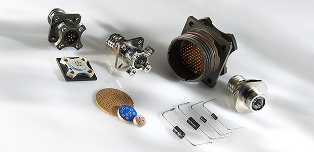
Filtering can be performed at a system control unit or nodal points of interconnects throughout the aircraft. While first filter connectors incorporated tubular components, planar array filter connectors surpass tubular types in performance, ease of manufacture, durability, and cost. TE has replaced its range of tubular connectors with planar versions. The array provides the required capacitance for each “through pin” and the inductance is provided by ferrite beads suitably positioned on either side of the array. Pi filter configurations require two planar arrays. The ground path for each capacitor is provided through the planar array and makes contact with the shell of the connector via a compliant grounding spring. Within limits, each filtered contact can have a different value of capacitance from its neighbor. One alternative – surface-mount components within the connector – provides lower costs, is more accommodating of changes in the capacitance footprint, and offers lower performance, especially in attenuating high frequencies. This technology is particularly suited to applications such as ground-based communications and industrial uses where high volume is present and conditions are expected to be less demanding.
Selecting the best filtering options begin with an EMI scan, which will identify the frequency and intensity of generated noise. Typically, TE engineers use the scan data to design a filter specifically for this specific noise environment. Most industry-standard aerospace connectors are available with filtering options. The receptacle connector is the most common and effective position to locate the filtering. A shielded receptacle offers the required low-impedance path to ground for optimum performance. Filtered receptacles also help in minimizing RF windows in the chassis due to the continuous ground plane inside. Filters are also available as adapters to allow a quick retrofit for poor behaving systems. The adapter is simply a filtered assembly with a plug on one end and a receptacle on the other. The cable is unplugged, the adapter is plugged into the receptacle, and the cable is reconnected.
The Fiber Alternative
The dielectric nature of optical fibers means they neither radiate nor receive EMI. As a medium for signal transport, they effectively remove EMI as an issue. Designers tend to be cautious about using fiber optics because of issues of cost, field reparability, and performance at extreme temperatures. Especially when the additional costs of shielding and filter for copper connectivity are considered, the economics of fiber optics becomes more favorable. As a high-speed backbone for in-flight entertainment and passenger network, fiber offers an attractive combination of high data rates and long transmission distances.
Conclusion
Fix it now – or fix it later. In the long run, designing for electromagnetic compatibility from the start saves headaches and unexpected costs down the road. Do not let a penny saved today incur costs of several pennies tomorrow. While size and weight remain critical issues in aircraft design and flight efficiency, components such as connectors and cable have become lighter and smaller, striking a balance between the additional weight of filters or shielding.