Designed for Smaller, Lighter, and Thinner Computing Devices
Across the globe, consumers and businesses are demanding increased access to the connected world. This demand is independent of where people are or what they are doing; it requires newer and smaller devices with faster connection speeds to allow people this access without significant effort. Designing and developing devices with these characteristics have posed unique challenges on original equipment manufacturers (OEMs) and component manufacturers.
TE Connectivity is at the forefront of this development in interconnect solutions designed to help OEMs meet such challenges. Examples of such interconnect solutions include the module card and the expansion card. These are used to add any number of features such as Wi-Fi, WWAN, Bluetooth, GPS, and solid state storage drives (SSDs) in devices such as PCs, laptops, tablets, and gaming devices.
Within the PCI-SIG industry standards group, there has been a natural progression from the previous generation of PCI Express Mini Card connectors with the M.2 (next-generation form factor, or NGFF) connector. To support the key attributes around OEM device development, the M.2 connector was designed taking speed and space savings into consideration.
Accelerating Speed
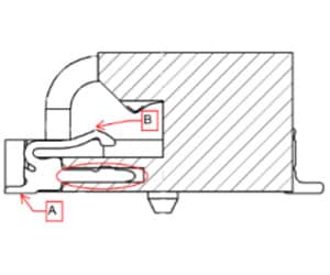
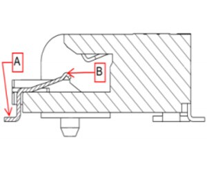
The M.2 connector was built for fast speeds targeting the need to meet the latest industry specifications like PCI Express 3.0, USB 3.0, and SATA 3.0. The high-speed capability of the M.2 connector comes from its optimized contact designs on both the upper and lower portions of the connector. The signal travels from the printed circuit board (PCB) connection point (Point A in Figures 1, 2) to the module card connection point (Point B in Figures 1, 2) and vice versa. The PCIe Mini Card connector features stamped contacts, which have large metal sections (red oval in Figure 1) used to retain the contacts within the housing. Since these large sections are not on the direct path from A to B (or B to A), they can be referred to as a signal stub. This signal stub increases capacitance in this area and generates noise coupling, reducing the contact performance at higher frequencies. The M.2 connector contacts (shown in Figure 2) have stamped and formed contacts, which eliminate the large signal stub. This very direct signal path allows for much better capacitance across the signal trace and improves performance.
Looking at differential insertion loss plots as a comparison, the PCIe Mini Card Connector crosses the -2dB point around 6.75GHz (shown in Figure 3), while the M.2 connector maintains under -2dB loss all the way through 12GHz (Figure 4), leaving room to support performance beyond the latest specs of PCIe 3.0, USB 3.0, and SATA 3.0.
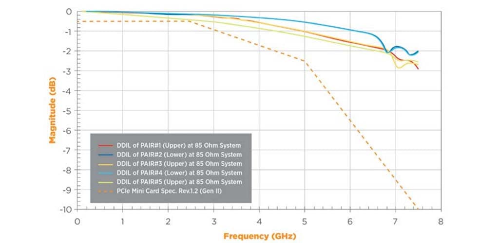
Figure 3: Differential Insertion Loss of PCI Express Mini Card Connector at 85 Ω
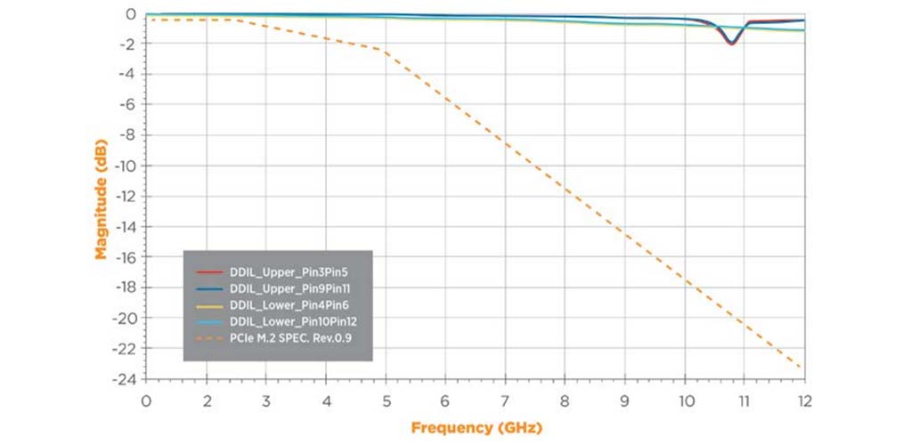
Figure 4: Differential Insertion Loss of M.2 Connector 2.25H at 85 Ω
Saving Space
The M.2 connector is also built for saving space. From the smaller 0.5mm pitch, compared to 0.8mm pitch for the PCIe Mini Card connector, the M.2 connector helps to save over 20% of PCB real estate. The height of the connector is also reduced from less than 4mm down to as low as 2.25mm for single-sided module cards. For double-sided module cards, the M.2 connector is as low as 3.2mm, which is still a reduction of 20% over that of the PCIe Mini Card.
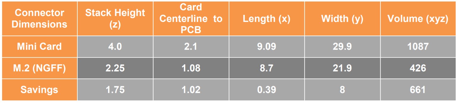
Table 1: Mini Card Connector versus M.2 Connector
Improvements over the PCIe Mini Card Connector
One aspect of the TE Connectivity M.2 connector design is the three-step, angled insertion
process. This process (shown in Figure 5) allows for two improvements over the PCIe Mini
Card connector. The first improvement is the bonus PCB real estate near the module card
screw-down. Having the module card seated at a 25° angle allows for taller components
near this screw-down area and greater design flexibility and potential space savings for the
OEM. If the module card were to be seated parallel to the mother board, taller components
could interfere with the insertion path. The second improvement is the module card insertion
process for the operators. As the insertion process is manual, having the operator’s hand higher
off the motherboard reduces the chances for potential damage to the components on the
motherboard.
The performance benefits of the M.2 connector are already measureable as the module card
market designed for the M.2 connector platform is in its infancy, the true performance limits
of the connector may not be fully known for some time to come. As the module card market
continues to develop and grow, the performance of the M.2 connector is expected to
separate itself further from the PCIe Mini Card connector platform.
The M.2 connector is another example of TE Connectivity leading the way in the consumer
electronics connectivity market. With a global pool of design and manufacturing engineering
expertise, solid relationships with key customers, and presence on many of the industry
standards committees, TE will continue to develop smaller, faster, better solutions for
increasingly demanding requirements.
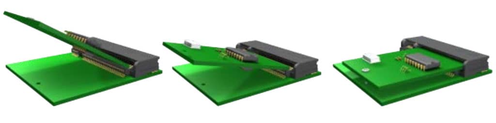
Figure 5: The M.2 Connector’s Three-Step Insertion Process


Designed for Smaller, Lighter, and Thinner Computing Devices
Across the globe, consumers and businesses are demanding increased access to the connected world. This demand is independent of where people are or what they are doing; it requires newer and smaller devices with faster connection speeds to allow people this access without significant effort. Designing and developing devices with these characteristics have posed unique challenges on original equipment manufacturers (OEMs) and component manufacturers.
TE Connectivity is at the forefront of this development in interconnect solutions designed to help OEMs meet such challenges. Examples of such interconnect solutions include the module card and the expansion card. These are used to add any number of features such as Wi-Fi, WWAN, Bluetooth, GPS, and solid state storage drives (SSDs) in devices such as PCs, laptops, tablets, and gaming devices.
Within the PCI-SIG industry standards group, there has been a natural progression from the previous generation of PCI Express Mini Card connectors with the M.2 (next-generation form factor, or NGFF) connector. To support the key attributes around OEM device development, the M.2 connector was designed taking speed and space savings into consideration.
Accelerating Speed
The M.2 connector was built for fast speeds targeting the need to meet the latest industry specifications like PCI Express 3.0, USB 3.0, and SATA 3.0. The high-speed capability of the M.2 connector comes from its optimized contact designs on both the upper and lower portions of the connector. The signal travels from the printed circuit board (PCB) connection point (Point A in Figures 1, 2) to the module card connection point (Point B in Figures 1, 2) and vice versa. The PCIe Mini Card connector features stamped contacts, which have large metal sections (red oval in Figure 1) used to retain the contacts within the housing. Since these large sections are not on the direct path from A to B (or B to A), they can be referred to as a signal stub. This signal stub increases capacitance in this area and generates noise coupling, reducing the contact performance at higher frequencies. The M.2 connector contacts (shown in Figure 2) have stamped and formed contacts, which eliminate the large signal stub. This very direct signal path allows for much better capacitance across the signal trace and improves performance.
Looking at differential insertion loss plots as a comparison, the PCIe Mini Card Connector crosses the -2dB point around 6.75GHz (shown in Figure 3), while the M.2 connector maintains under -2dB loss all the way through 12GHz (Figure 4), leaving room to support performance beyond the latest specs of PCIe 3.0, USB 3.0, and SATA 3.0.
Figure 3: Differential Insertion Loss of PCI Express Mini Card Connector at 85 Ω
Figure 4: Differential Insertion Loss of M.2 Connector 2.25H at 85 Ω
Saving Space
The M.2 connector is also built for saving space. From the smaller 0.5mm pitch, compared to 0.8mm pitch for the PCIe Mini Card connector, the M.2 connector helps to save over 20% of PCB real estate. The height of the connector is also reduced from less than 4mm down to as low as 2.25mm for single-sided module cards. For double-sided module cards, the M.2 connector is as low as 3.2mm, which is still a reduction of 20% over that of the PCIe Mini Card.
Table 1: Mini Card Connector versus M.2 Connector
Improvements over the PCIe Mini Card Connector
One aspect of the TE Connectivity M.2 connector design is the three-step, angled insertion
process. This process (shown in Figure 5) allows for two improvements over the PCIe Mini
Card connector. The first improvement is the bonus PCB real estate near the module card
screw-down. Having the module card seated at a 25° angle allows for taller components
near this screw-down area and greater design flexibility and potential space savings for the
OEM. If the module card were to be seated parallel to the mother board, taller components
could interfere with the insertion path. The second improvement is the module card insertion
process for the operators. As the insertion process is manual, having the operator’s hand higher
off the motherboard reduces the chances for potential damage to the components on the
motherboard.
The performance benefits of the M.2 connector are already measureable as the module card
market designed for the M.2 connector platform is in its infancy, the true performance limits
of the connector may not be fully known for some time to come. As the module card market
continues to develop and grow, the performance of the M.2 connector is expected to
separate itself further from the PCIe Mini Card connector platform.
The M.2 connector is another example of TE Connectivity leading the way in the consumer
electronics connectivity market. With a global pool of design and manufacturing engineering
expertise, solid relationships with key customers, and presence on many of the industry
standards committees, TE will continue to develop smaller, faster, better solutions for
increasingly demanding requirements.
Figure 5: The M.2 Connector’s Three-Step Insertion Process