Understand relay-coil inductance to determine the energy released by the coil upon de-energization
Relay users often desire to know the inductance of the relay coil they are using so they can determine the energy released by the coil upon de-energization.
Coil inductance with armature seated is greater than that when unseated. This is because inductance varies directly with incremental permeability ( µ ) and inversely with the length ( l ) of the magnetic circuit path. The air gap in the magnetic circuit of an unseated armature both decreases µ and increases l. Of course, the greater the inductance, the greater the energy released into the coil circuit upon deenergization.
Inductance also will vary with coil voltage, since permeability varies with magnetizing force which, in turn, is determined by coil voltage. For values most meaningful to the circuit designer, inductance should be measured under conditions that simulate actual relay service; that is, at rated voltage and current.
Inductance with armature seated represents actual application conditions at the instant coil power is removed. When coil power is removed, the coil generates a counter voltage, -e = L(di/dt), which is fed back into the switch circuit. Depending on energy levels, this voltage surge may adversley affect the life or operational characteristics of the switch that controls the relay coil. ( For methods to protect the switch, see "Coil Suppression Can Reduce Relay Life", 13C3264.)
The inductance of DC coils should be measured by the L = tR method by use of an oscilloscope. This method requires the application of rated DC voltage to the coil while physically holding the armature seated. The value, t, is the time for coil current to increase to .623 of its steady state value, and R is the coil DC resistance in ohms as measured by an ohmmeter.
The inductance of AC coils may be determined by measuring coil voltage and current and actual power consumed by use of a wattmeter. The product of coil voltage and current is the "VA" in the following equation, "W" is the power as given by the wattmeter. R = measured DC resistance in ohms.
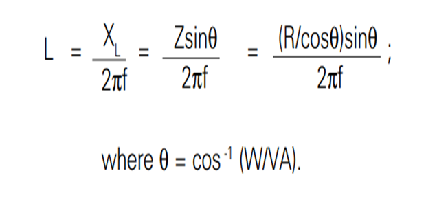
If a wattmeter isn't available, inductance may be determined by use of a dual-trace oscilloscope, one input of which is fed by a current probe. In this method, rated voltage at the proper frequency is impressed on the coil, and the time displacement, t, of applied voltage and coil current is measured by the oscilloscope. Inductance is calculated as above, where:
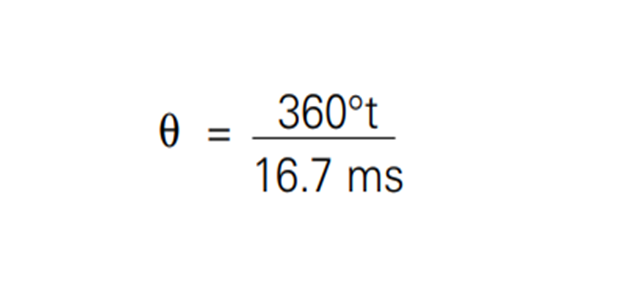
t = time in ms by which coil current lags coil voltage
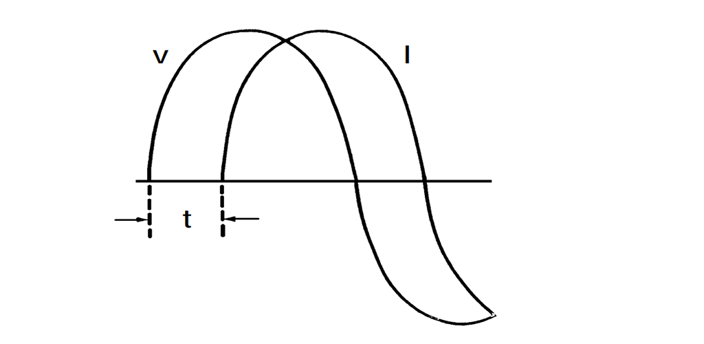
Figure 1.
Understand relay-coil inductance to determine the energy released by the coil upon de-energization
Relay users often desire to know the inductance of the relay coil they are using so they can determine the energy released by the coil upon de-energization.
Coil inductance with armature seated is greater than that when unseated. This is because inductance varies directly with incremental permeability ( µ ) and inversely with the length ( l ) of the magnetic circuit path. The air gap in the magnetic circuit of an unseated armature both decreases µ and increases l. Of course, the greater the inductance, the greater the energy released into the coil circuit upon deenergization.
Inductance also will vary with coil voltage, since permeability varies with magnetizing force which, in turn, is determined by coil voltage. For values most meaningful to the circuit designer, inductance should be measured under conditions that simulate actual relay service; that is, at rated voltage and current.
Inductance with armature seated represents actual application conditions at the instant coil power is removed. When coil power is removed, the coil generates a counter voltage, -e = L(di/dt), which is fed back into the switch circuit. Depending on energy levels, this voltage surge may adversley affect the life or operational characteristics of the switch that controls the relay coil. ( For methods to protect the switch, see "Coil Suppression Can Reduce Relay Life", 13C3264.)
The inductance of DC coils should be measured by the L = tR method by use of an oscilloscope. This method requires the application of rated DC voltage to the coil while physically holding the armature seated. The value, t, is the time for coil current to increase to .623 of its steady state value, and R is the coil DC resistance in ohms as measured by an ohmmeter.
The inductance of AC coils may be determined by measuring coil voltage and current and actual power consumed by use of a wattmeter. The product of coil voltage and current is the "VA" in the following equation, "W" is the power as given by the wattmeter. R = measured DC resistance in ohms.
If a wattmeter isn't available, inductance may be determined by use of a dual-trace oscilloscope, one input of which is fed by a current probe. In this method, rated voltage at the proper frequency is impressed on the coil, and the time displacement, t, of applied voltage and coil current is measured by the oscilloscope. Inductance is calculated as above, where:
t = time in ms by which coil current lags coil voltage
Figure 1.