Improve load-life performance
Introduction
(NOTE: Applies to DC coils switching AC loads only)
Incandescent lamps, inductive loads like motors and solenoids, capacitive loads like electronic ballasts and switching power supplies, etc. can exhibit very high initial surge currents upon energizing. This can be up to 10X the steady state current or more and is especially troublesome should the contact closure randomly occur near the peak of the voltage sine-wave. Welding of contacts due to such excessive surge current is often the result. Relays for such applications usually need to be oversized or specially designed to handle the high inrush current relative to the relatively modest steady state current. This usually results in extra control cost and increased space usage.
Similarly, because the breaking contact arc usually extinguishes only when the high current sine-wave transitions through zero and reverses polarity, synchronization must be based on zero-crossing of the voltage waveforms on “make” and the current waveform on “break”. In the case of loads with unity power-factor (resistive, lamp, etc.), there is no phase shift and so voltage based sensing of zero-crossing can be used for both “make” and break” synchronization.
Properly implemented, maximum peak-current capability can be increased by approximately 8-10X, switching life at a given load can potentially be increased approximately 8-10X and maximum load at a given switching life can also potentially be increased up to 5X or so (as long as it does not exceed the maximum current the relay is capable of carrying).
Even on non-reactive loads with unity power factor and little initial surge current, significant load-life performance improvement can be achieved.
NOTE: Also see cautions about switching iron-core inductive loads in the “Sync on Contact Closure (Make)” and “Special Make/Break Considerations for Inductive Loads” sections following.
Switching of Contacts Phase-Synced to Load Power
(NOTE: Applies to DC coils switching AC loads only)
Also see “Special Make/Break Considerations for Inductive Loads” following.
There are various ways to enhance relay performance when switching some load types by using synchronization of the “make” and “break” timing of the contacts to the AC voltage and/or current sine-wave. This only works for DC coil types because there are parts of the AC sine wave where there is insufficient energy to effect operation of an AC coil relay or contactor.
Properly implemented, contact switching life and especially ability to handle high inrush loads is markedly increased. Inrush current capacity and load switching life improvements of approximately 10X are often achievable depending upon accurate implementation and other factors in the specific application.
Some of these techniques and their advantages and limitations are discussed below:
- Sync On Contact Closure (Make):
When the contact closure is synchronized to just before or just after the zero-crossing point of the voltage waveform, the relay contact does not make much current or voltage and so longer contact life can be expected as well as increased ability to handle loads with high starting currents (because the voltage and current ramps up from zero following the sine wave so maximum peak current is seldom seen during the time the relay contact is closing and stabilizing).
This is accomplished by driving the relay coil at a time (offset from a subsequent zero-voltage crossing by the operate time of the relay) so that the relay contact always “makes” just before or just after the zero point (usually +/- 1 milli-second of zero is acceptable and achievable).
Since relay operate times vary by relay family, from relay to relay, lot to lot and over the life of the relay, this is best implemented using micro-controllers where the actual operate time of the relay is monitored and the offset time adjusted to very accurately hit the zero-cross point via a moving average or 8 to 10 operations. Operate time variation can also be minimized by overdriving the coil at 125% or 150% of nominal voltage (not recommended if switching max. rated current). The operate bounce time should also be considered in the timing calculation.
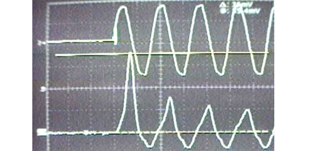
Example 1. 1/10 Hp Inducer Fan Motor energized at 0° on the voltage waveform. Top is voltage, bottom is current. Note the very high first half-cycle current surge.
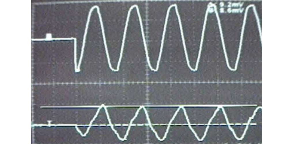
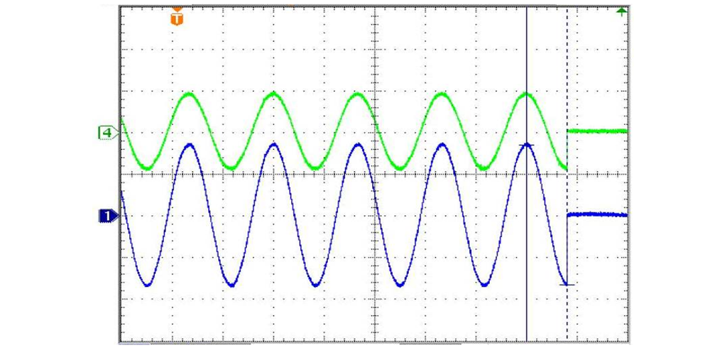
Example 2. The same 1/10 Hp Inducer Fan Motor energized at 90° on the voltage waveform. Top waveform is voltage, bottom waveform is current. Note there is no excessive first half-cycle current surge. For most inductive loads, the best make point is at about 75° before peak but each load type should be measured to see what works best. The exact value used is not critical so anything in the 70-90° range is usually acceptable.
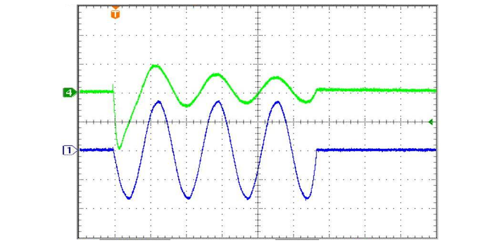
Example 3a. Make Incandescent Lamp at Zero.
Most non-inductive loads should be energized very near zero-voltage for maximum contact performance. Doing so minimizes the current surge during the interval the contact is closing and stabilizing thereby reducing the chance of tack-welding. This is especially critical on high inrush current loads such as incandescent lamps, electronic lamp ballasts, switching power supplies, etc.
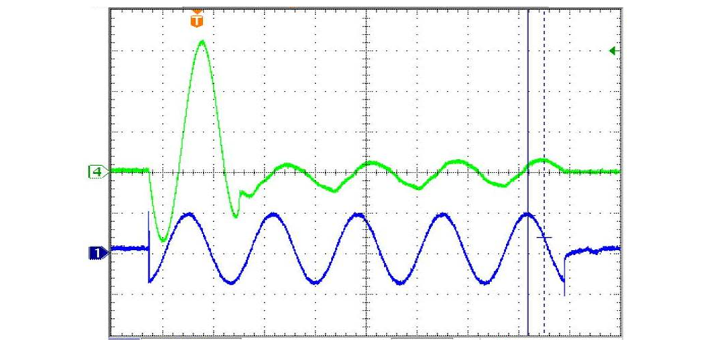
Example 3a shows an incandescent lamp switched on very near zero-voltage so that the current ramps up following the AC sine wave. Example 3b shows the same load switched on at peak voltage - with a resultant high inrush current as high voltage is applied to the cold lamp filament. Such high inrush currents greatly increase the risk of tack-welding the contact as it closes and stabilizes. Similarly, high currents are common on capacitive loads as well when switched near peak voltage.
Example 3b. Make Incandescent Lamp at peak.
- Sync on Contact Opening (Break):
Similarly, when the contact opening is synchronized to occur just before (usually -1/2 / +0 milli-seconds is acceptable and achievable), but never after the zerocrossing point of the current waveform, the relay contact does not “break” much current or voltage and the arc will then extinguish at the imminent zero-crossing greatly reducing contact erosion and wear. For non-inductive loads, where there is no phase differential between voltage and current, breaking at zero-voltage is just as acceptable and yields a simpler control design.
Also see “Special Make/Break Considerations for Inductive Loads” following.
Example 4a. Break Incandescent Lamp at peak.
Example 4b. Break Incandescent Lamp at Zero.
Obviously, in the case of resistive or incandescent loads, break of the contact just before zero voltage or current yields less breaking arc intensity and longer contact life.
- Special Make/Break Considerations for Inductive loads
Inductive loads (especially those with iron cores) must be handled differently because they have tendencies to high inrush current on make and to generating a severe contact arc and high transient voltages on break.
Unlike non-inductive loads, where make of the contact very near zero-crossing is desirable, inductive loads (especially iron-core inductors like transformers and solenoids) should never make at zero-crossing. Doing so will drive the inductor into saturation resulting in a very high initial current surge. Such inductive loads perform better when driven at about 75° on the AC voltage waveform. Each load is a bit different so each should be monitored and adjusted for best performance.
Performance while breaking inductive loads is especially improved. This is due to greatly reduced arc-erosion of the contact material due to lower breaking-arc intensity and duration. Similarly, due to very little energy being stored in the load inductance at the time the contact breaks, electromagnetic interference(EMI) and reverse-voltage transients generated are of decreased intensity so adverse effects on sensitive electronics is minimized. This is accomplished by removing the relay coil drive at a time (offset from a subsequent zero-current crossing by the release time of the relay) so that the relay contact always “breaks” just before (but never after) the zero point (usually -1/2 / +0 milli-seconds is acceptable and achievable).
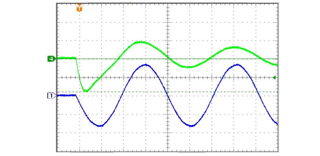
Example 5a. Make Inductive Load at PEAK VOLTAGE - Break Inductive Load at ZERO CURRENT. (NOTE: Phase of current lags voltage.)
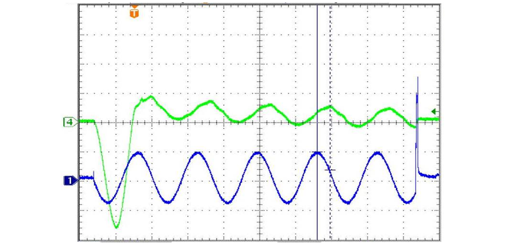
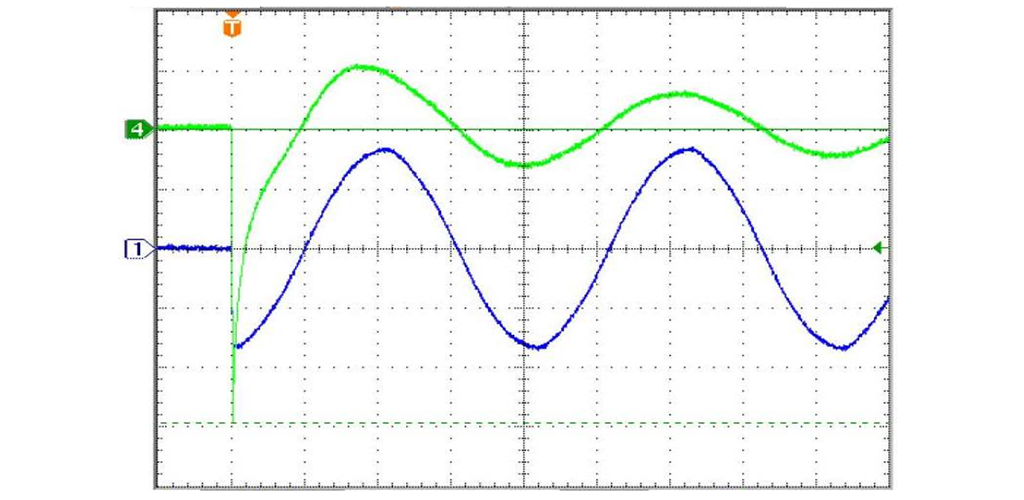
Example 5b. MAKE Inductive Load at ZERO VOLTAGE - BREAK Inductive Load at PEAK CURRENT (NOTE: Phase of current lags voltage.)
Summary
Synchronizing contact make and break to the load voltage and current can yield marked improvement in performance when properly implemented. However if the technique is incorrectly implemented, degradation of performance can also occur due to material transfer or accelerated contact erosion. TE Engineering should always be consulted to obtain implementation advice for each type relay.
Since relay operate and release times vary by relay family, from relay to relay, lot to lot and over the life of the relay, this is best implemented using micro-controllers where the actual operate and release times of the relay are monitored with respect to the voltage (and current if breaking inductive loads) waveform and the offset time adjusted periodically. This is the best way to ensure accurate switching over the life of the relay.
Make at +/-1 milli-second around zero voltage and break at - 1/2 / +0 milli-seconds before zero current is acceptable and achievable. On non-inductive loads, synchronization to zero voltage on break yields acceptable performance and a simpler control design.
It is important to note that the effect of temperature on the resistance of the relay coil wire, and so operate voltage and operate/release timing, must be compensated for. This is discussed in Application Notes “Proper Coil Drive is Critical to Good Relay and Contactor Performance” and “Coil Voltage and Temperature Compensation.
Improve load-life performance
Introduction
(NOTE: Applies to DC coils switching AC loads only)
Incandescent lamps, inductive loads like motors and solenoids, capacitive loads like electronic ballasts and switching power supplies, etc. can exhibit very high initial surge currents upon energizing. This can be up to 10X the steady state current or more and is especially troublesome should the contact closure randomly occur near the peak of the voltage sine-wave. Welding of contacts due to such excessive surge current is often the result. Relays for such applications usually need to be oversized or specially designed to handle the high inrush current relative to the relatively modest steady state current. This usually results in extra control cost and increased space usage.
Similarly, because the breaking contact arc usually extinguishes only when the high current sine-wave transitions through zero and reverses polarity, synchronization must be based on zero-crossing of the voltage waveforms on “make” and the current waveform on “break”. In the case of loads with unity power-factor (resistive, lamp, etc.), there is no phase shift and so voltage based sensing of zero-crossing can be used for both “make” and break” synchronization.
Properly implemented, maximum peak-current capability can be increased by approximately 8-10X, switching life at a given load can potentially be increased approximately 8-10X and maximum load at a given switching life can also potentially be increased up to 5X or so (as long as it does not exceed the maximum current the relay is capable of carrying).
Even on non-reactive loads with unity power factor and little initial surge current, significant load-life performance improvement can be achieved.
NOTE: Also see cautions about switching iron-core inductive loads in the “Sync on Contact Closure (Make)” and “Special Make/Break Considerations for Inductive Loads” sections following.
Switching of Contacts Phase-Synced to Load Power
(NOTE: Applies to DC coils switching AC loads only)
Also see “Special Make/Break Considerations for Inductive Loads” following.
There are various ways to enhance relay performance when switching some load types by using synchronization of the “make” and “break” timing of the contacts to the AC voltage and/or current sine-wave. This only works for DC coil types because there are parts of the AC sine wave where there is insufficient energy to effect operation of an AC coil relay or contactor.
Properly implemented, contact switching life and especially ability to handle high inrush loads is markedly increased. Inrush current capacity and load switching life improvements of approximately 10X are often achievable depending upon accurate implementation and other factors in the specific application.
Some of these techniques and their advantages and limitations are discussed below:
- Sync On Contact Closure (Make):
When the contact closure is synchronized to just before or just after the zero-crossing point of the voltage waveform, the relay contact does not make much current or voltage and so longer contact life can be expected as well as increased ability to handle loads with high starting currents (because the voltage and current ramps up from zero following the sine wave so maximum peak current is seldom seen during the time the relay contact is closing and stabilizing).
This is accomplished by driving the relay coil at a time (offset from a subsequent zero-voltage crossing by the operate time of the relay) so that the relay contact always “makes” just before or just after the zero point (usually +/- 1 milli-second of zero is acceptable and achievable).
Since relay operate times vary by relay family, from relay to relay, lot to lot and over the life of the relay, this is best implemented using micro-controllers where the actual operate time of the relay is monitored and the offset time adjusted to very accurately hit the zero-cross point via a moving average or 8 to 10 operations. Operate time variation can also be minimized by overdriving the coil at 125% or 150% of nominal voltage (not recommended if switching max. rated current). The operate bounce time should also be considered in the timing calculation.
Example 1. 1/10 Hp Inducer Fan Motor energized at 0° on the voltage waveform. Top is voltage, bottom is current. Note the very high first half-cycle current surge.
Example 2. The same 1/10 Hp Inducer Fan Motor energized at 90° on the voltage waveform. Top waveform is voltage, bottom waveform is current. Note there is no excessive first half-cycle current surge. For most inductive loads, the best make point is at about 75° before peak but each load type should be measured to see what works best. The exact value used is not critical so anything in the 70-90° range is usually acceptable.
Example 3a. Make Incandescent Lamp at Zero.
Most non-inductive loads should be energized very near zero-voltage for maximum contact performance. Doing so minimizes the current surge during the interval the contact is closing and stabilizing thereby reducing the chance of tack-welding. This is especially critical on high inrush current loads such as incandescent lamps, electronic lamp ballasts, switching power supplies, etc.
Example 3a shows an incandescent lamp switched on very near zero-voltage so that the current ramps up following the AC sine wave. Example 3b shows the same load switched on at peak voltage - with a resultant high inrush current as high voltage is applied to the cold lamp filament. Such high inrush currents greatly increase the risk of tack-welding the contact as it closes and stabilizes. Similarly, high currents are common on capacitive loads as well when switched near peak voltage.
Example 3b. Make Incandescent Lamp at peak.
- Sync on Contact Opening (Break):
Similarly, when the contact opening is synchronized to occur just before (usually -1/2 / +0 milli-seconds is acceptable and achievable), but never after the zerocrossing point of the current waveform, the relay contact does not “break” much current or voltage and the arc will then extinguish at the imminent zero-crossing greatly reducing contact erosion and wear. For non-inductive loads, where there is no phase differential between voltage and current, breaking at zero-voltage is just as acceptable and yields a simpler control design.
Also see “Special Make/Break Considerations for Inductive Loads” following.
Example 4a. Break Incandescent Lamp at peak.
Example 4b. Break Incandescent Lamp at Zero.
Obviously, in the case of resistive or incandescent loads, break of the contact just before zero voltage or current yields less breaking arc intensity and longer contact life.
- Special Make/Break Considerations for Inductive loads
Inductive loads (especially those with iron cores) must be handled differently because they have tendencies to high inrush current on make and to generating a severe contact arc and high transient voltages on break.
Unlike non-inductive loads, where make of the contact very near zero-crossing is desirable, inductive loads (especially iron-core inductors like transformers and solenoids) should never make at zero-crossing. Doing so will drive the inductor into saturation resulting in a very high initial current surge. Such inductive loads perform better when driven at about 75° on the AC voltage waveform. Each load is a bit different so each should be monitored and adjusted for best performance.
Performance while breaking inductive loads is especially improved. This is due to greatly reduced arc-erosion of the contact material due to lower breaking-arc intensity and duration. Similarly, due to very little energy being stored in the load inductance at the time the contact breaks, electromagnetic interference(EMI) and reverse-voltage transients generated are of decreased intensity so adverse effects on sensitive electronics is minimized. This is accomplished by removing the relay coil drive at a time (offset from a subsequent zero-current crossing by the release time of the relay) so that the relay contact always “breaks” just before (but never after) the zero point (usually -1/2 / +0 milli-seconds is acceptable and achievable).
Example 5a. Make Inductive Load at PEAK VOLTAGE - Break Inductive Load at ZERO CURRENT. (NOTE: Phase of current lags voltage.)
Example 5b. MAKE Inductive Load at ZERO VOLTAGE - BREAK Inductive Load at PEAK CURRENT (NOTE: Phase of current lags voltage.)
Summary
Synchronizing contact make and break to the load voltage and current can yield marked improvement in performance when properly implemented. However if the technique is incorrectly implemented, degradation of performance can also occur due to material transfer or accelerated contact erosion. TE Engineering should always be consulted to obtain implementation advice for each type relay.
Since relay operate and release times vary by relay family, from relay to relay, lot to lot and over the life of the relay, this is best implemented using micro-controllers where the actual operate and release times of the relay are monitored with respect to the voltage (and current if breaking inductive loads) waveform and the offset time adjusted periodically. This is the best way to ensure accurate switching over the life of the relay.
Make at +/-1 milli-second around zero voltage and break at - 1/2 / +0 milli-seconds before zero current is acceptable and achievable. On non-inductive loads, synchronization to zero voltage on break yields acceptable performance and a simpler control design.
It is important to note that the effect of temperature on the resistance of the relay coil wire, and so operate voltage and operate/release timing, must be compensated for. This is discussed in Application Notes “Proper Coil Drive is Critical to Good Relay and Contactor Performance” and “Coil Voltage and Temperature Compensation.