A Near-Field 2.4GHz Ring Antenna for High Data Rate & High Security Data Transmission in Short Range for Rotational Joint
ABSTRACT
Nowadays the security camera uses slip ring for both the power and data link from the rotating camera to the surveillance infrastructure. There are reliability issue and installation complexity. Therefore, the contactless power and data link solution is required to improve the reliability and reduce the complexity. While the contactless power for the camera could be achieved by the induction coupling for the short range, the data link presents several challenges. In order to achieve reliable transmission of the H.264 high-resolution video stream, the WiFi protocol with at least 54Mbps is proposed. However, in order to achieve this high data rate during the rotation of the camera, a good signal reception of the receiving antenna must be achieved during the whole course of rotation in 360 degrees. On the other hand, in order to achieve high security level, the signal leakage must be retained below a certain level to avoid capturing the video by an eavesdropping device nearby. That means we need to develop an antenna with low return loss |S11|, high reception signal ratio |S12| and lower leakage signal P_leak, which are sometimes contradicting in antenna design. By using electromagnetic simulation tool ANSYS HFSS, a 2.4GHz ring near-field antenna with circular polarization is developed. The proposed antenna consists of a ring of microstrip transmission line and a RF load. By terminating the transmission line with the 50ohm RF resistor, the antenna performs as a traveling wave antenna and is omnidirectional in pattern and circularly polarized. In worst case, the proposed antenna has the impedance bandwidth with return loss |S11|= -15dB, the reception signal strength ratio with |S12| = -26dB, and the captured signal ratio with P_tx = -56dB covering the operational band of 2.4-2.49GHz during the whole rotating course for phi=0-180 degree. Comparing to the conventional resonant antenna which has |S11|=-8dB, |S12|=-37dB and the captured signal ratio with P_tx = -35dB in the worst case, the proposed antenna has superior advantage with 7dB better in return loss, 11dB in reception signal and 21dB in leakage. The measurement results also confirm the advantages. This antenna will be applied in customer’s wireless camera using contactless powering, wherein the video signal transmitted and received efficiently between two antennas while the information security is guaranteed with very low signal leakage to the surrounding. Thus, the reliability and security can be both achieved and guaranteed for the security camera.
PROBLEM STATEMENT
The challenges of designing antennas for wireless cameras using contactless power include:
- Limited space. The width of antenna is only 6mm maximally as the antenna need be at least 4mm from induction coil which is used for contactless powering.
- The camera rotates around the axis to monitor the surrounding so that the received power needs to keep constant when transmitting antenna rotates. For a conventional antenna, it is difficult to meet this requirement for 2 reasons:
- The received power is inversely proportional to the square of distance between transmitter antenna (Tx) and receiver antenna (Rx).
- Antenna Tx and antenna Rx are linear polarized and polarization mismatch occurs when Tx antenna rotates.
3. As the requirement as a security camera from the customer, the leakage power radiated by the antenna to the surrounding needs to be very low so that a standard antenna can’t intercept the communication signal.
Therefore, we need to design an antenna which is short in width, its electromagnetic field power concentrates in nearby and uniformly distributed along its length. In addition, the antenna needs to be circular-polarized to avoid any polarization mismatch between 2 such antenna during rotation. By using ANSYS HFSS, a ring antenna consists of a microstrip line of narrow ground and a 50ohm RF resistor is developed to address these challenges. The measurement results of the antenna prototypes based on the simulation has verified that the customers’ requirements are met.
METHODS AND RESULTS
Build simulation model in ANSYS HFSS and fabricate samples
The simulation model of the antenna is built in ANSYS HFSS environment. The geometry of the proposed antenna is given in Fig.1 (a) and (b). The main body of the antenna is a circular microstrip line terminated with a 50ohm RF resistor. The microstrip line has a conductor of width w1 printed on one side of an inexpensive FR4 substrate of thickness d=0.762mm and has another conductor of width w2=6mm on the other side of the substrate. The inner and the outer radii of the FR4 sub are R1=50mm and R2=60.5mm respectively. Lumped port is applied on one end of the microstrip line as feed source and the port impedance is 50ohm. At the other end of the transmission line, a lumped 50ohm resistor is modeled.
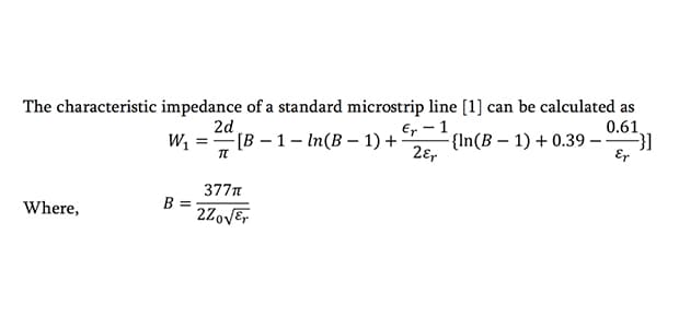
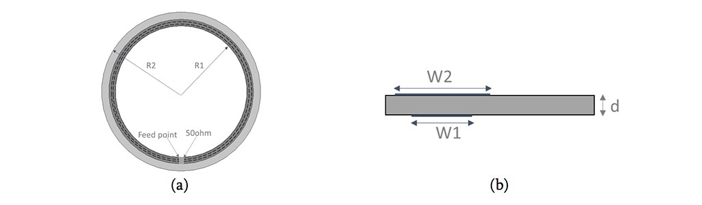
Figure 1. Geometry of proposed antenna: (a) Top view; (b) cross-section.
From formula (1), the width of signal trace of the proposed microstrip line W1 can be determined and the value needs be further optimized by EM simulation software. Fig.2 shows the prototype of proposed antenna, one rigid cable with SMA connector is connected with one end of the circular microstrip line and an RF load is connected with the other end.

Performance of the proposed antenna
Fig.3 shows the simplified simulation model in HFSS of the security camera with both contactless power and data link. The camera is on the lower part which rotates around the metal shaft in the center. The upper part is fixed with the power supply and image data center. The power transmitter (PTx) composed of the power transmitting circuit and PTx coil and the WiFi receiver composed of wireless circuit and antenna Rx are accommodated in the upper part, while the power receiver (PRx) and the WiFi transmitter are located in the lower part. In the structure, the PTx coil and the PRx coil are used for contactless powering. The coils should be placed in the simulation model because they have effect on the antenna performance.
The antenna has been investigated and designed through simulation with HFSS to save the cut-and-trail cost and time. Once the antenna with good performance has been achieved, the antenna prototypes are made to verify the simulation. For this design, 2 samples are made and tested using Keysight vector network analyzer E5071C and Satimo 32 probes anechoic chamber.
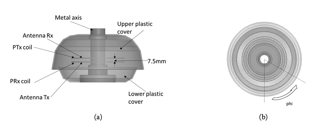
Figure 3. Structure of a wireless camera: (a) Front view; (b) Top view (phi=0 indicates position where feed points of two antenna overlap with each other in top view).
Fig.4 illustrates the power distribution relationship between the antenna and the surrounding, where P_tx is the input power into antenna Tx, P_rx is the received power by antenna Rx, P_leak is the leakage power to the surrounding, P_capture is the received power by a virtual standard dipole antenna 30cm away from the wireless camera. Among these parameters, the relationship between P_capture and P_leak is
P_capture = P_leak +Path loss of 30cm (2)
Where,
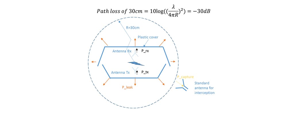
Figure 4. Power distribution relationship between antenna and the surrounding.
Fig.5 gives the simulation and measurement results of the return loss of the antenna. It can be seen that |S11| is better than -15dB in the operation band 2.4-2.49GHz and constant at rotation angles phi = 0, 90, and 180. It indicates that the antenna has good matching during the whole rotation course.
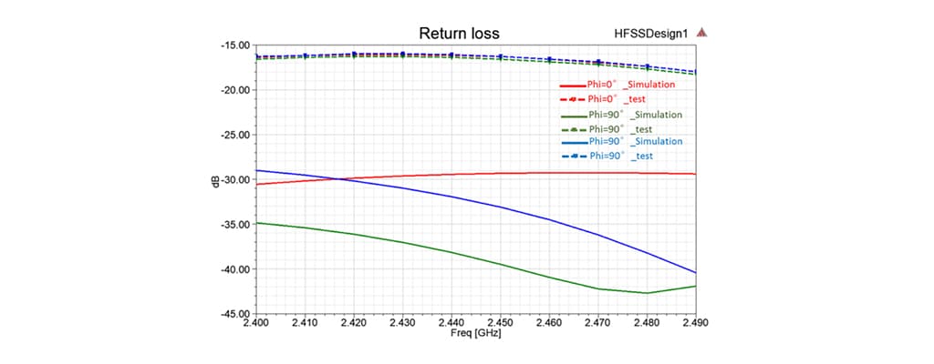
Figure 5. Return loss of proposed antenna in a wireless camera during rotation.
Fig.6(a) displays the power received by Rx antenna and Fig.6(b) the power captured by the standard dipole antenna 30cm away. We can see that the lowest power received by Antenna Rx from Antenna Tx is -26dB and the maximal captured power by the virtual standard antenna is -56dB in the worst case. The received power is 30dB higher than that captured by the virtual standard antenna. In addition, the P_rx has a low variation when the lower part of the wireless camera rotates around the axis. If P_tx is set to be -35dBm, then P_rx > -60dBm, and P_capture < -91dBm, and the system will have good wireless communication while very low leakage power for interception.
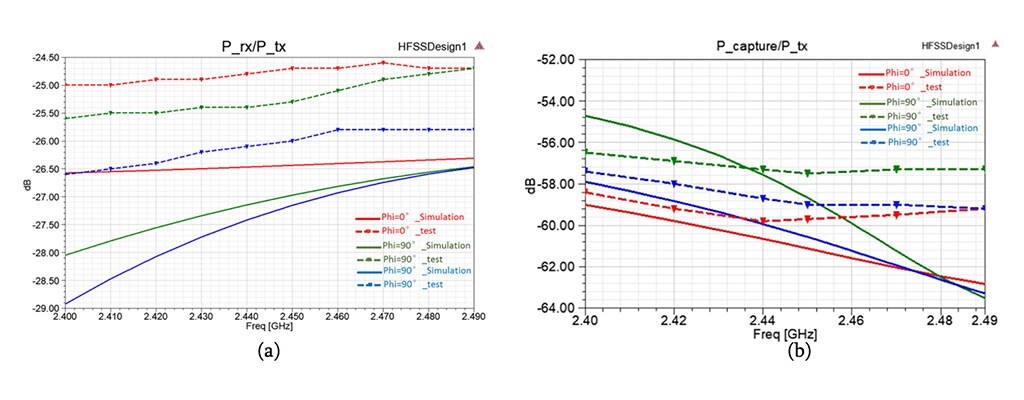
Figure 6. (a) Power received by proposed antenna Tx normalized by P_tx; (b) Power captured by an imaginary standard antenna normalized by P_tx.
Comparison with conventional antenna
Because most of the WiFi antenna in the market for such applications are conventional resonant antenna, such as dipoles, IFAs, PIFAs, etc. In order to prove the proposed antenna is superior to conventional antenna in performance, the dipole antenna [2] shown Fig.7 with operation frequency band covering 2.4-2.49GHz are used to replace the proposed antenna in the same camera model as in Fig.3 and the simulation results are derived for comparison (the upper and lower covers are hidden in the model).
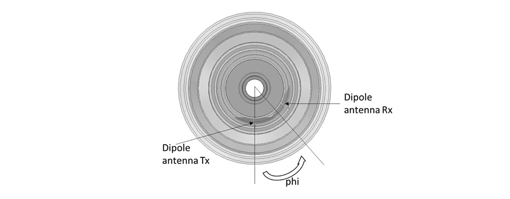
Figure 7. A wireless camera using 2 dipole antenna for communication (phi=0 indicates position where feed points of two antenna overlap with each other in top view).
From simulation results, it is seen that the dipole antenna is not a near-field antenna so it can’t achieve good impedance matching when it operates in near-field during rotation as demonstrated in Fig.8. The return loss varies with 3dB during the rotation from phi = 0 to 180, which make the matching to the WiFi receiver circuit is challenging in the whole course of rotation.
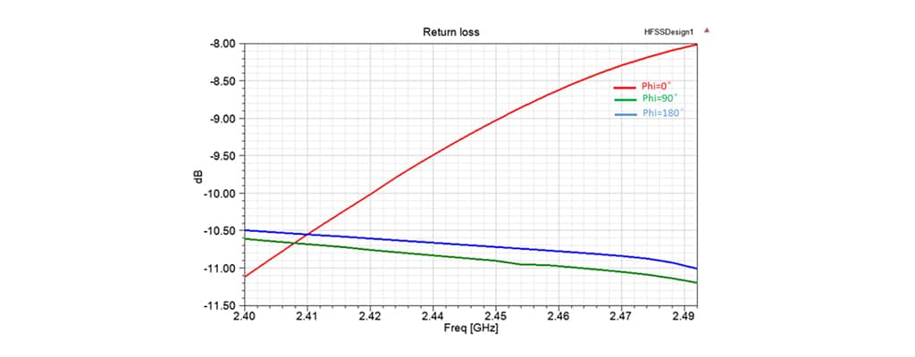
Figure 8. Return loss of a dipole antenna in a wireless camera during rotation.
Fig. 9(a) shows that P_rx/P_tx varies significantly as Antenna Tx rotates, especially, when phi changes from 0°to 180°, P_rx/P_tx reduces greatly from -5dB to -35dB. The reasons are:
- When Antenna Tx rotates, the path loss between the two antenna varies greatly as center-to-center distance changes.
- The dipole antenna is linearly polarized, when Antenna Tx rotates, severe polarization mismatch occurs.
Fig.9 (b) shows that the maximal captured leakage power radiated by the dipole to the surrounding is as high as -35dB which is 21dB higher than the proposed antenna. The reason is that the conventional dipole antenna is a resonant far-field antenna which has intrinsically strong far-field radiation. Therefore, the resonant far-field antennas in other types are also impractical for such short-range high rate data link with requirement on low captured power for security reason.
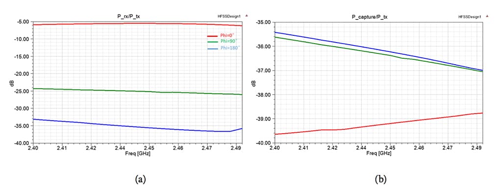
Figure 9. (a) Power received by dipole antenna Tx normalized by P_tx; (b) Power leaked and captured by a virtual standard antenna normalized by P_tx.
DISCUSSION AND KEY POINTS
Conclusions
A near-field circular-polarized ring antenna has been designed using ANSYS HFSS simulation tool and verified by the measurement of the sample. The antenna is a circular microstrip line terminated with a 50ohm RF resistor. the proposed antenna can achieve good impedance match in the operation band from 2.4 to 2.49GHz. It is demonstrated by the simulation and measurement results that it can provide good data link and low leakage to the surrounding. Our proposed antenna could be a promising solution for high data rate and high security data link applications which becomes more and more with the increase installation and application of using video stream from cameras for security monitoring as well as automatic run machines and cars.
In addition, as this antenna is a traveling antenna, the near-field electric field and magnetic field are uniformly distributed along the periphery with near-field circular polarization thus provide stable and constant data link during the rotation which makes it a perfect alternative of the slip rings with high safety and reliability in a very wide frequency band.
Further Study and Works
After getting the antenna performance from simulation and prototype test, the active test with WiFi chipset and contactless powering module on PCB will be made to validate the antenna and system performance.
There is a wide use of the near-field antenna in appliance, industry and other areas. The proposed antenna is quite suitable for rotatable devices using contactless powering. Future study and work will be optimizing the antenna performance and designing shielding for the system to reduce the leakage power further to avoid interception.
REFERENCES
[1] David M. Pozar, “Microwave Engineering, Fourth Edition”, page149, John Wiley & Sons, Inc.
[2]Ramesh Garg, Prakash Bhartia, Inder Bahl, Apisak Ittipiboon, “Microstrip Antenna Design Handbook”, page399, Artech House
A Near-Field 2.4GHz Ring Antenna for High Data Rate & High Security Data Transmission in Short Range for Rotational Joint
ABSTRACT
Nowadays the security camera uses slip ring for both the power and data link from the rotating camera to the surveillance infrastructure. There are reliability issue and installation complexity. Therefore, the contactless power and data link solution is required to improve the reliability and reduce the complexity. While the contactless power for the camera could be achieved by the induction coupling for the short range, the data link presents several challenges. In order to achieve reliable transmission of the H.264 high-resolution video stream, the WiFi protocol with at least 54Mbps is proposed. However, in order to achieve this high data rate during the rotation of the camera, a good signal reception of the receiving antenna must be achieved during the whole course of rotation in 360 degrees. On the other hand, in order to achieve high security level, the signal leakage must be retained below a certain level to avoid capturing the video by an eavesdropping device nearby. That means we need to develop an antenna with low return loss |S11|, high reception signal ratio |S12| and lower leakage signal P_leak, which are sometimes contradicting in antenna design. By using electromagnetic simulation tool ANSYS HFSS, a 2.4GHz ring near-field antenna with circular polarization is developed. The proposed antenna consists of a ring of microstrip transmission line and a RF load. By terminating the transmission line with the 50ohm RF resistor, the antenna performs as a traveling wave antenna and is omnidirectional in pattern and circularly polarized. In worst case, the proposed antenna has the impedance bandwidth with return loss |S11|= -15dB, the reception signal strength ratio with |S12| = -26dB, and the captured signal ratio with P_tx = -56dB covering the operational band of 2.4-2.49GHz during the whole rotating course for phi=0-180 degree. Comparing to the conventional resonant antenna which has |S11|=-8dB, |S12|=-37dB and the captured signal ratio with P_tx = -35dB in the worst case, the proposed antenna has superior advantage with 7dB better in return loss, 11dB in reception signal and 21dB in leakage. The measurement results also confirm the advantages. This antenna will be applied in customer’s wireless camera using contactless powering, wherein the video signal transmitted and received efficiently between two antennas while the information security is guaranteed with very low signal leakage to the surrounding. Thus, the reliability and security can be both achieved and guaranteed for the security camera.
PROBLEM STATEMENT
The challenges of designing antennas for wireless cameras using contactless power include:
- Limited space. The width of antenna is only 6mm maximally as the antenna need be at least 4mm from induction coil which is used for contactless powering.
- The camera rotates around the axis to monitor the surrounding so that the received power needs to keep constant when transmitting antenna rotates. For a conventional antenna, it is difficult to meet this requirement for 2 reasons:
- The received power is inversely proportional to the square of distance between transmitter antenna (Tx) and receiver antenna (Rx).
- Antenna Tx and antenna Rx are linear polarized and polarization mismatch occurs when Tx antenna rotates.
3. As the requirement as a security camera from the customer, the leakage power radiated by the antenna to the surrounding needs to be very low so that a standard antenna can’t intercept the communication signal.
Therefore, we need to design an antenna which is short in width, its electromagnetic field power concentrates in nearby and uniformly distributed along its length. In addition, the antenna needs to be circular-polarized to avoid any polarization mismatch between 2 such antenna during rotation. By using ANSYS HFSS, a ring antenna consists of a microstrip line of narrow ground and a 50ohm RF resistor is developed to address these challenges. The measurement results of the antenna prototypes based on the simulation has verified that the customers’ requirements are met.
METHODS AND RESULTS
Build simulation model in ANSYS HFSS and fabricate samples
The simulation model of the antenna is built in ANSYS HFSS environment. The geometry of the proposed antenna is given in Fig.1 (a) and (b). The main body of the antenna is a circular microstrip line terminated with a 50ohm RF resistor. The microstrip line has a conductor of width w1 printed on one side of an inexpensive FR4 substrate of thickness d=0.762mm and has another conductor of width w2=6mm on the other side of the substrate. The inner and the outer radii of the FR4 sub are R1=50mm and R2=60.5mm respectively. Lumped port is applied on one end of the microstrip line as feed source and the port impedance is 50ohm. At the other end of the transmission line, a lumped 50ohm resistor is modeled.
Figure 1. Geometry of proposed antenna: (a) Top view; (b) cross-section.
From formula (1), the width of signal trace of the proposed microstrip line W1 can be determined and the value needs be further optimized by EM simulation software. Fig.2 shows the prototype of proposed antenna, one rigid cable with SMA connector is connected with one end of the circular microstrip line and an RF load is connected with the other end.
Performance of the proposed antenna
Fig.3 shows the simplified simulation model in HFSS of the security camera with both contactless power and data link. The camera is on the lower part which rotates around the metal shaft in the center. The upper part is fixed with the power supply and image data center. The power transmitter (PTx) composed of the power transmitting circuit and PTx coil and the WiFi receiver composed of wireless circuit and antenna Rx are accommodated in the upper part, while the power receiver (PRx) and the WiFi transmitter are located in the lower part. In the structure, the PTx coil and the PRx coil are used for contactless powering. The coils should be placed in the simulation model because they have effect on the antenna performance.
The antenna has been investigated and designed through simulation with HFSS to save the cut-and-trail cost and time. Once the antenna with good performance has been achieved, the antenna prototypes are made to verify the simulation. For this design, 2 samples are made and tested using Keysight vector network analyzer E5071C and Satimo 32 probes anechoic chamber.
Figure 3. Structure of a wireless camera: (a) Front view; (b) Top view (phi=0 indicates position where feed points of two antenna overlap with each other in top view).
Fig.4 illustrates the power distribution relationship between the antenna and the surrounding, where P_tx is the input power into antenna Tx, P_rx is the received power by antenna Rx, P_leak is the leakage power to the surrounding, P_capture is the received power by a virtual standard dipole antenna 30cm away from the wireless camera. Among these parameters, the relationship between P_capture and P_leak is
P_capture = P_leak +Path loss of 30cm (2)
Where,
Figure 4. Power distribution relationship between antenna and the surrounding.
Fig.5 gives the simulation and measurement results of the return loss of the antenna. It can be seen that |S11| is better than -15dB in the operation band 2.4-2.49GHz and constant at rotation angles phi = 0, 90, and 180. It indicates that the antenna has good matching during the whole rotation course.
Figure 5. Return loss of proposed antenna in a wireless camera during rotation.
Fig.6(a) displays the power received by Rx antenna and Fig.6(b) the power captured by the standard dipole antenna 30cm away. We can see that the lowest power received by Antenna Rx from Antenna Tx is -26dB and the maximal captured power by the virtual standard antenna is -56dB in the worst case. The received power is 30dB higher than that captured by the virtual standard antenna. In addition, the P_rx has a low variation when the lower part of the wireless camera rotates around the axis. If P_tx is set to be -35dBm, then P_rx > -60dBm, and P_capture < -91dBm, and the system will have good wireless communication while very low leakage power for interception.
Figure 6. (a) Power received by proposed antenna Tx normalized by P_tx; (b) Power captured by an imaginary standard antenna normalized by P_tx.
Comparison with conventional antenna
Because most of the WiFi antenna in the market for such applications are conventional resonant antenna, such as dipoles, IFAs, PIFAs, etc. In order to prove the proposed antenna is superior to conventional antenna in performance, the dipole antenna [2] shown Fig.7 with operation frequency band covering 2.4-2.49GHz are used to replace the proposed antenna in the same camera model as in Fig.3 and the simulation results are derived for comparison (the upper and lower covers are hidden in the model).
Figure 7. A wireless camera using 2 dipole antenna for communication (phi=0 indicates position where feed points of two antenna overlap with each other in top view).
From simulation results, it is seen that the dipole antenna is not a near-field antenna so it can’t achieve good impedance matching when it operates in near-field during rotation as demonstrated in Fig.8. The return loss varies with 3dB during the rotation from phi = 0 to 180, which make the matching to the WiFi receiver circuit is challenging in the whole course of rotation.
Figure 8. Return loss of a dipole antenna in a wireless camera during rotation.
Fig. 9(a) shows that P_rx/P_tx varies significantly as Antenna Tx rotates, especially, when phi changes from 0°to 180°, P_rx/P_tx reduces greatly from -5dB to -35dB. The reasons are:
- When Antenna Tx rotates, the path loss between the two antenna varies greatly as center-to-center distance changes.
- The dipole antenna is linearly polarized, when Antenna Tx rotates, severe polarization mismatch occurs.
Fig.9 (b) shows that the maximal captured leakage power radiated by the dipole to the surrounding is as high as -35dB which is 21dB higher than the proposed antenna. The reason is that the conventional dipole antenna is a resonant far-field antenna which has intrinsically strong far-field radiation. Therefore, the resonant far-field antennas in other types are also impractical for such short-range high rate data link with requirement on low captured power for security reason.
Figure 9. (a) Power received by dipole antenna Tx normalized by P_tx; (b) Power leaked and captured by a virtual standard antenna normalized by P_tx.
DISCUSSION AND KEY POINTS
Conclusions
A near-field circular-polarized ring antenna has been designed using ANSYS HFSS simulation tool and verified by the measurement of the sample. The antenna is a circular microstrip line terminated with a 50ohm RF resistor. the proposed antenna can achieve good impedance match in the operation band from 2.4 to 2.49GHz. It is demonstrated by the simulation and measurement results that it can provide good data link and low leakage to the surrounding. Our proposed antenna could be a promising solution for high data rate and high security data link applications which becomes more and more with the increase installation and application of using video stream from cameras for security monitoring as well as automatic run machines and cars.
In addition, as this antenna is a traveling antenna, the near-field electric field and magnetic field are uniformly distributed along the periphery with near-field circular polarization thus provide stable and constant data link during the rotation which makes it a perfect alternative of the slip rings with high safety and reliability in a very wide frequency band.
Further Study and Works
After getting the antenna performance from simulation and prototype test, the active test with WiFi chipset and contactless powering module on PCB will be made to validate the antenna and system performance.
There is a wide use of the near-field antenna in appliance, industry and other areas. The proposed antenna is quite suitable for rotatable devices using contactless powering. Future study and work will be optimizing the antenna performance and designing shielding for the system to reduce the leakage power further to avoid interception.
REFERENCES
[1] David M. Pozar, “Microwave Engineering, Fourth Edition”, page149, John Wiley & Sons, Inc.
[2]Ramesh Garg, Prakash Bhartia, Inder Bahl, Apisak Ittipiboon, “Microstrip Antenna Design Handbook”, page399, Artech House