Defining design criteria for coil drive circuitry and the selection of relay coils
Introduction
Relay and contactor coils are usually wound using copper wire - and copper wire has a positive temperature coefficient as shown in the formulas and chart following. Most coils are also powered by a relatively fixed voltage. Thus, assuming the voltage remains constant, increasing temperature will result in higher coil resistance and decreased coil current.
Magnetic field strength in such devices depends directly upon Ampere Turns (AT) (i.e. the number of turns of wire multiplied by the current flowing through that wire) within the coil. A fixed voltage and increased temperature yields decreased AT and therefore decreased magnetic field strength. In order for the relay or contactor to reliably operate and hold over time, sufficient AT must always be maintained under worst case conditions of temperature, coil resistance, winding tolerance and supply voltage tolerance. If not, the relay will fail to operate at all, will operate softly with low contact force, or drop out (release) unexpectedly. All of which are detrimental to good relay performance.
Because the number of “turns” of wire on the coil are not normally specified in datasheets, all these corrections must be calculated based on temperatures, resistances and voltages which are specified or can be measured.
Following are more details defining important design criteria for coil drive circuitry and selection of relay coils, a step by step guide to the process and some useful formulas. Also refer to Application Note “Proper Coil Drive is Critical to Good Relay and Contactor Performance”.
Analysis
Proper coil drive is critically important for proper relay operation and load/life performance. In order for a relay (or contactor) to function properly, it is necessary to confirm that the coil is properly driven so that the contacts close properly and remain closed, and the armature seats fully and remains seated, over all conditions that might be encountered over time in the application.
Relays are electro-magnets, and the strength of the magnetic field operating them is a function of ampere-turns (AT). Since the number of “turns” cannot change once wound, the only application variable is the coil current.
DC coil current is solely determined by the applied voltage and the coil resistance. If voltage decreases or resistance increases, coil current decreases - resulting in lower AT and less magnetic force in the coil.
AC coil current is similarly affected by applied voltage and coil impedance - but the impedance(Z) is defined as Z=sqrt(R2 + XL2 ) so changes to coil resistance alone have a somewhat less direct effect on AC coils than on DC coils.
The applied coil voltage will also vary as the power supply varies over time. The control designer must define the input voltage range over which the control must operate (typically +10%/-20% of nominal) and then compensate in the control design to assure proper operation over that voltage range.
Similarly, coil resistance will have a manufacturing tolerance (typically +/-5% or +/-10%) at room temperature - but the resistance of the wire also has a positive temperature coefficient so coil resistance will increase as wire temperature increases or decrease as wire temperature decreases. Useful formulas follow:
Effect of Temperature on Coil Resistance
Coil resistance change over temperature: Rf = Ri((Tf + 234.5) / (Ti + 234.5)) (Graphically following:)
Coil Resistance Factor vs. Coil Temperature
(Based on 20 degrees C = 1 using copper wire
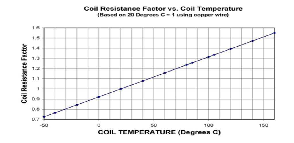
COIL TEMPERATURE (Degrees C)
* Operate voltage corrected for temperature change
Vf = Vo(Rf/Ri)
* Actual coil temperature by “change-of-resistance” method
Tf = Ti + Rf/Ri(k+Tri) – (k+Trt) [k = 234.5 for copper wire]
Using the above formulas and basic algebra, one can:
- Calculate the expected resistance change over temperature
(be sure to include not only ambient temperature but the effect of self-heating within the coil and the heating due to internal load-carrying components as well).
- Calculate the expected change in operate voltage
- Calculate the increase in actual coil temperature - and so coil resistance from one condition to another (i.e. - room ambient temperature unpowered, no-load to elevated ambient temperature with coil powered and contacts fully loaded).
Nomenclature definition for above formulas:
- Ri = Coil resistance at initial coil temperature
- Rf = Coil resistance at final coil temperature
- Ti = Initial coil temperature
- Tf = Final coil temperature
- Tri =Ambient temperature at start of test
- Trt =Ambient temperature at end of test
- Vo = Original “operate” voltage
- Vf = Final operate voltage (corrected for coil temperature change.
“Ambient” temperature is the temperature in the vicinity of the relay - this is not the same as the temperature in the vicinity of the assembly or enclosure containing the relay.
Similarly, “initial coil temperature” and “initial ambient temperature” may not be exactly the same at the start of the test unless sufficient time has elapsed to stabilize both temperatures.
Because coils and other components have thermal mass, sufficient time must be allowed for all temperatures to stabilize before measurements are recorded.
Correcting DC Coil Voltage for Worst Case Conditions
(Note: DC coil relays are always assumed to be powered by well filtered DC - not unfiltered half-wave or full-wave unless specifically noted. Furthermore, datasheet information, such as coil resistance, is assumed to be specified at room temperature (approx. 23°C unless otherwise noted).
Worst case relay operating conditions are at minimum supply voltage and maximum coil resistance at the highest operating ambient temperature under the highest contact current loading.
The designer should then correct the input voltage to adjust for the increased coil resistance and decreased AT so that, worst case there is still enough AT to operate the relay and fully seat the armature. This will ensure that full force is applied on the contacts. If the contact is closed but the armature not seated, the contact force will be low and so the contact(s) will be subject to overheating and prone to tackwelding upon application of high currents.
Since the internal heating from the coil and from the load on the contacts is not easily calculated, the most accurate way to begin this calculation is to take a sample relay of the same type and rated coil voltage and follow these steps:
- Measure the coil resistance “Ri” at room temperature and record the room temperature parameters “Ti” and “Tri” for later use.
- Load the contact to maximum current and apply nominal voltage to the coil.
- Wait until the coil temperature has stabilized (i.e. until the coil resistance has stopped changing) then measure the “hot” coil resistance “Rf”. This will then tell how much “temperature rise” occurred in the coil due to coil and contact currents. Also measure any change in the ambient temperature and record that as the “Trt” value for use later.
- Next, add in the difference between room temperature and the maximum expected ambient temperature to the loaded coil resistance above. Using the “Rf” formula or the chart, correct the “hot” coil resistance measured above for the increased ambient temperature. This becomes the corrected “Rf” value.
- Using the preceding formula “Vf = Vo(Rf/Ri)”, calculate the new value for “Vf”, using the minimum operating voltage provided in the datasheet. (i.e. nominal coil voltage minus the negative tolerance on the minimum operate voltage provided in the datasheet (usually 80% of nominal) for DC coils).
- This gives the minimum voltage that must be applied to the relay coil to provide proper operation under the worst operating conditions.
AC Coil Correction
- Note: AC coils are corrected similarly while remembering that the resistance(R) change affects the AC coil impedance by the formula Z=sqrt(R2 + XL 2 ) rather than linearly so that the effect on coil current, and thus AT, is similarly non-linear. Reference TE Application Note “Proper Coil Drive is Critical to Good Relay and Contactor Performance” paragraph titled “Characteristics of AC Coil Relays and Contactors”.
Conclusion
Consult TE Product Engineering for assistance in the event that an acceptable mix of applied voltage range and available coil values is not compatible with the ambient temperature range needed in the application.
Disclaimer
TE has made every reasonable effort to confirm the accuracy of the information set forth herein; however, TE does not guarantee that it is error-free nor does TE make any other representation, warranty, or guarantee that the information is accurate, correct, reliable or current. TE EXPRESSLY DISCLAIMS ALL WARRANTIES REGARDING THE INFORMATION CONTAINED HEREIN, WHETHER EXPRESS, IMPLIED OR STATUTORY, INCLUDING ANY IMPLIED WARRANTIES OR MERCHANTABILITY OR FITNESS FOR A PARTICULAR PURPOSE. In no event will TE be liable for any direct, indirect, incidental, special or consequential damages arising from or related to Recipient’s use of the information.
Defining design criteria for coil drive circuitry and the selection of relay coils
Introduction
Relay and contactor coils are usually wound using copper wire - and copper wire has a positive temperature coefficient as shown in the formulas and chart following. Most coils are also powered by a relatively fixed voltage. Thus, assuming the voltage remains constant, increasing temperature will result in higher coil resistance and decreased coil current.
Magnetic field strength in such devices depends directly upon Ampere Turns (AT) (i.e. the number of turns of wire multiplied by the current flowing through that wire) within the coil. A fixed voltage and increased temperature yields decreased AT and therefore decreased magnetic field strength. In order for the relay or contactor to reliably operate and hold over time, sufficient AT must always be maintained under worst case conditions of temperature, coil resistance, winding tolerance and supply voltage tolerance. If not, the relay will fail to operate at all, will operate softly with low contact force, or drop out (release) unexpectedly. All of which are detrimental to good relay performance.
Because the number of “turns” of wire on the coil are not normally specified in datasheets, all these corrections must be calculated based on temperatures, resistances and voltages which are specified or can be measured.
Following are more details defining important design criteria for coil drive circuitry and selection of relay coils, a step by step guide to the process and some useful formulas. Also refer to Application Note “Proper Coil Drive is Critical to Good Relay and Contactor Performance”.
Analysis
Proper coil drive is critically important for proper relay operation and load/life performance. In order for a relay (or contactor) to function properly, it is necessary to confirm that the coil is properly driven so that the contacts close properly and remain closed, and the armature seats fully and remains seated, over all conditions that might be encountered over time in the application.
Relays are electro-magnets, and the strength of the magnetic field operating them is a function of ampere-turns (AT). Since the number of “turns” cannot change once wound, the only application variable is the coil current.
DC coil current is solely determined by the applied voltage and the coil resistance. If voltage decreases or resistance increases, coil current decreases - resulting in lower AT and less magnetic force in the coil.
AC coil current is similarly affected by applied voltage and coil impedance - but the impedance(Z) is defined as Z=sqrt(R2 + XL2 ) so changes to coil resistance alone have a somewhat less direct effect on AC coils than on DC coils.
The applied coil voltage will also vary as the power supply varies over time. The control designer must define the input voltage range over which the control must operate (typically +10%/-20% of nominal) and then compensate in the control design to assure proper operation over that voltage range.
Similarly, coil resistance will have a manufacturing tolerance (typically +/-5% or +/-10%) at room temperature - but the resistance of the wire also has a positive temperature coefficient so coil resistance will increase as wire temperature increases or decrease as wire temperature decreases. Useful formulas follow:
Effect of Temperature on Coil Resistance
Coil resistance change over temperature: Rf = Ri((Tf + 234.5) / (Ti + 234.5)) (Graphically following:)
Coil Resistance Factor vs. Coil Temperature
(Based on 20 degrees C = 1 using copper wire
COIL TEMPERATURE (Degrees C)
* Operate voltage corrected for temperature change
Vf = Vo(Rf/Ri)
* Actual coil temperature by “change-of-resistance” method
Tf = Ti + Rf/Ri(k+Tri) – (k+Trt) [k = 234.5 for copper wire]
Using the above formulas and basic algebra, one can:
- Calculate the expected resistance change over temperature
(be sure to include not only ambient temperature but the effect of self-heating within the coil and the heating due to internal load-carrying components as well).
- Calculate the expected change in operate voltage
- Calculate the increase in actual coil temperature - and so coil resistance from one condition to another (i.e. - room ambient temperature unpowered, no-load to elevated ambient temperature with coil powered and contacts fully loaded).
Nomenclature definition for above formulas:
- Ri = Coil resistance at initial coil temperature
- Rf = Coil resistance at final coil temperature
- Ti = Initial coil temperature
- Tf = Final coil temperature
- Tri =Ambient temperature at start of test
- Trt =Ambient temperature at end of test
- Vo = Original “operate” voltage
- Vf = Final operate voltage (corrected for coil temperature change.
“Ambient” temperature is the temperature in the vicinity of the relay - this is not the same as the temperature in the vicinity of the assembly or enclosure containing the relay.
Similarly, “initial coil temperature” and “initial ambient temperature” may not be exactly the same at the start of the test unless sufficient time has elapsed to stabilize both temperatures.
Because coils and other components have thermal mass, sufficient time must be allowed for all temperatures to stabilize before measurements are recorded.
Correcting DC Coil Voltage for Worst Case Conditions
(Note: DC coil relays are always assumed to be powered by well filtered DC - not unfiltered half-wave or full-wave unless specifically noted. Furthermore, datasheet information, such as coil resistance, is assumed to be specified at room temperature (approx. 23°C unless otherwise noted).
Worst case relay operating conditions are at minimum supply voltage and maximum coil resistance at the highest operating ambient temperature under the highest contact current loading.
The designer should then correct the input voltage to adjust for the increased coil resistance and decreased AT so that, worst case there is still enough AT to operate the relay and fully seat the armature. This will ensure that full force is applied on the contacts. If the contact is closed but the armature not seated, the contact force will be low and so the contact(s) will be subject to overheating and prone to tackwelding upon application of high currents.
Since the internal heating from the coil and from the load on the contacts is not easily calculated, the most accurate way to begin this calculation is to take a sample relay of the same type and rated coil voltage and follow these steps:
- Measure the coil resistance “Ri” at room temperature and record the room temperature parameters “Ti” and “Tri” for later use.
- Load the contact to maximum current and apply nominal voltage to the coil.
- Wait until the coil temperature has stabilized (i.e. until the coil resistance has stopped changing) then measure the “hot” coil resistance “Rf”. This will then tell how much “temperature rise” occurred in the coil due to coil and contact currents. Also measure any change in the ambient temperature and record that as the “Trt” value for use later.
- Next, add in the difference between room temperature and the maximum expected ambient temperature to the loaded coil resistance above. Using the “Rf” formula or the chart, correct the “hot” coil resistance measured above for the increased ambient temperature. This becomes the corrected “Rf” value.
- Using the preceding formula “Vf = Vo(Rf/Ri)”, calculate the new value for “Vf”, using the minimum operating voltage provided in the datasheet. (i.e. nominal coil voltage minus the negative tolerance on the minimum operate voltage provided in the datasheet (usually 80% of nominal) for DC coils).
- This gives the minimum voltage that must be applied to the relay coil to provide proper operation under the worst operating conditions.
AC Coil Correction
- Note: AC coils are corrected similarly while remembering that the resistance(R) change affects the AC coil impedance by the formula Z=sqrt(R2 + XL 2 ) rather than linearly so that the effect on coil current, and thus AT, is similarly non-linear. Reference TE Application Note “Proper Coil Drive is Critical to Good Relay and Contactor Performance” paragraph titled “Characteristics of AC Coil Relays and Contactors”.
Conclusion
Consult TE Product Engineering for assistance in the event that an acceptable mix of applied voltage range and available coil values is not compatible with the ambient temperature range needed in the application.
Disclaimer
TE has made every reasonable effort to confirm the accuracy of the information set forth herein; however, TE does not guarantee that it is error-free nor does TE make any other representation, warranty, or guarantee that the information is accurate, correct, reliable or current. TE EXPRESSLY DISCLAIMS ALL WARRANTIES REGARDING THE INFORMATION CONTAINED HEREIN, WHETHER EXPRESS, IMPLIED OR STATUTORY, INCLUDING ANY IMPLIED WARRANTIES OR MERCHANTABILITY OR FITNESS FOR A PARTICULAR PURPOSE. In no event will TE be liable for any direct, indirect, incidental, special or consequential damages arising from or related to Recipient’s use of the information.