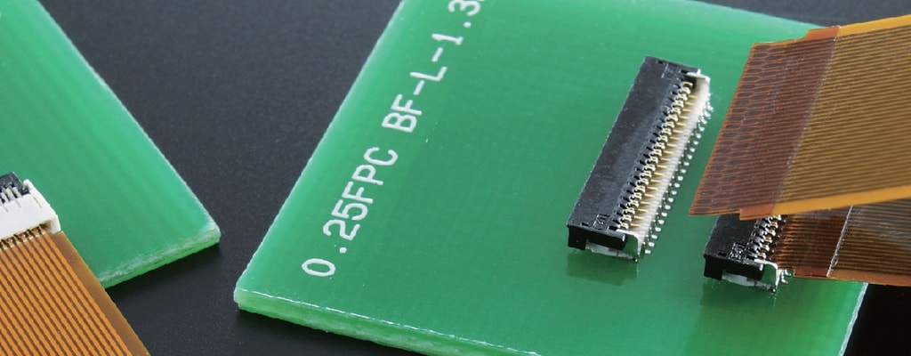
Fine Pitch FPC
Fine pitch flexible printed circuit (FPC) connectors are a great option for situations where small centerline spacing makes large wire-to-board interconnects impractical.
Our fine pitch FPC solutions are reliable interconnects that use an actuator to secure the cable termination so no tooling is required. Consider the following advantages and aspects of FPC connectors when designing for smaller centerline, lower profile heights, and lighter interconnect solutions.
Tail Orientation
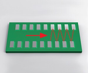
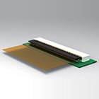
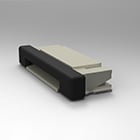
All of our fine pitch FPC products feature a staggered tail orientation. This orientation type means that the layout of the front and rear contacts are staggered as illustrated in Figure A.
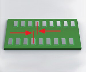
When the tail orientation is staggered, it is important to remember that you can measure the centerline by measuring the distance between the center of the front contact and the center of the rear contact as illustrated in Figure B.
Centerline Spacing
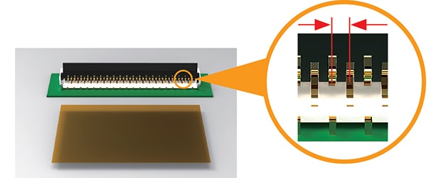
Centerline can be measured many different ways, however, in general it is simply the spacing between the center of one contact and the center of the contact next to it.
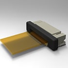
You can note the centerline of our fine pitch FPC product by looking at the contacts of the connector itself, shown in Figure C, or by the method already described in Figure B.
Actuator Types
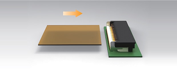
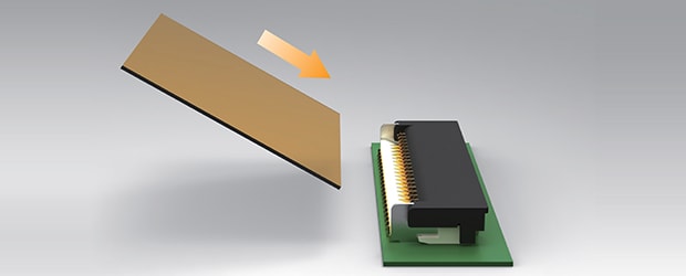
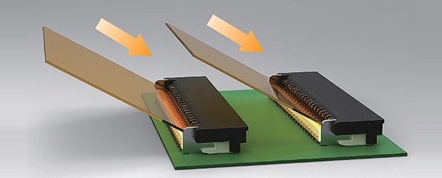
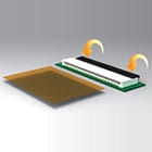
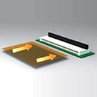
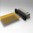
All of our fine pitch FPC connectors incorporate a flip lock actuator for greater printed circuit retention. This termination method also allows for zero insertion force, which is why this product is commonly referred to as a ZIF connector. The operation of a flip-lock actuator can be seen in the images below.
Front Flip-Lock Actuator
Back Flip-Lock Actuator

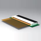
Stuffer Actuator (Plunger Style)


Contact Types
Many of our fine pitch FPC products are available in top, bottom, or dual contact versions. This attribute represents which portion of the contact the FPC interacts with. As you can see from the image below, the FPC contacts are formed in a “U” shape. Only one prong of that U-shaped contact interfaces with the FPC contacts. Choosing the correct contact design is generally based on the orientation of the flexible printed circuit, as described below.


Angled Insertion
What’s the advantage of angled insertion?