 e
e
 e
e
 e
e
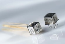
Product Overview
High-Performance Relays and Contactors
Q: What are the differences between TE's CII, Hartman, and Kilovac brands?
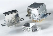
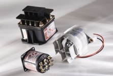
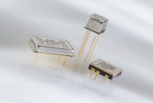
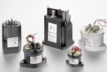
A: Our CII line of products covers both 28 volt DC and 155 volt AC relays, ranging from signal level to 50A hermetically sealed products. This product line is known as CII's “mid-range” brand. Included in this category are TO-5 style relays, crystal can relays, time delay relays, and MIL-qualified products. The HARTMAN portfolio provides both 28 volt DC and 115 volt AC contactors ranging from 25 amp to 1000 amp. Included in this category are 1PST to 3PDT environmentally seal devices. Our specialty KILOVAC brand includes high voltage DC hermetically sealed relays and contactors. Included in this category are 270Vdc to 70 KVdc devices rated from a few amps to 1000 amps.
Q: How do TE industrial relays compare to high-performance relays?
A: Industrial products (Potter & Brumfield, Axicom, and Schrack) will typically have a UL or CSA rating. High-performance products (CII, HARTMAN, and KILOVAC) will be generally screened to an in-house MIL type or custom baseline test procedure, or qualified to specs like M6106, M83726, M83536, and M39016. TE's industrial products are typically plastic-cased and environmentally sealed. High-performance products are generally hermetically/environmentally sealed and capped with a metal housing. Industrial relays are typically used in appliance, automotive, computer, and/or consumer products. High-performance devices are generally used in medical, aerospace, military, and harsh/high reliability environments.
Q: What is the advantage of using an economizer coil?
A: Typically used in a contactor, a mechanical economizer coil is a low current (high resistance) coil that is cut-in to hold the contacts closed after a high current (low resistance) pull-in coil transfers the contacts, reducing coil current draw and heat, while the contactor remains energized. As an option, an alternative method of pulse width modulation (PWM) for economizing can be utilized. For example, KILOVAC's EV series contactor use PWM or electronic economizer. The principal is similar to that of the mechanical economizer. This method is generally employed for coil hold power efficiency and heat reduction of the relay coil and overall structure. The PWM can be used in ground applications and is generally not used in critical flight or high reliability applications since it may create EMI concerns with sensitive equipment. In either case, the economized coil is a power saver with regards to hold current.
 e
e
 e
e
 e
e
 e
e
Technical Information
High-Performance Relays and Contactors
Q: Are TE high-performance relays and contactors position sensitive?
A: No. Our high-performance products are not position sensitive and can be securely mounted in any axial direction. But it is good to note the vibration and mechanical shock environments where the product will be used. Areas of high vibration or high shock could affect the overall performance of the relay over time.
Q: What is the load type, voltage, current, and frequency (AC only) that will be switched?
A: Resistive, motor, inductive, capacitive, or lamp loads are common application loads. Note: resistive ratings are generally used as the default current rating for a device. Other current levels will vary depending on the load type. For example, a relay with 10A, 28 VDC resistive rating may be rated at 8A for inductive load, 4A for motor load, and/or 2A lamp load. As for coil voltage requirements, the common coil ratings are 6, 12, or 28 Vdc or 115 VAC. Other voltage options are available by request.
Q: Do you require an electrically held (monostable) or latching (bistable) relay for the application?
A: Electrically held relays require constant coil power to engage, while latching devices only require a specified pulse to operate the relay. For example, a monostable (single coil) relay could be used in an A/C control system where the circuit would require constant power for the operation of the A/C unit. For a bistable (dual coil) relay, an application might include usage in a satellite where power needs to be conserved. A small, relatively short nominal voltage pulse to one or the other relay coil is sufficient to change the relay state. Each type has distinctive advantages and disadvantages and should be considered when selecting a device for a specific application.
Q: What is the desired relay contact configuration?
A: There are several variants of contact architectures, from SPST (single pole, single throw) to 4PDT (four pole, double throw) or higher, and configuration will be dependent on the application need and how many circuits require isolation/control. Also note, common relay contact nomenclature may also be written as Form A (SPST, normally open), Form B (SPST, normally closed), or Form C (SPDT, normally open and normally closed). A full list of contact combination forms and terminology can be found with the American National Standards Institute (ANSI).
Q: What are the desired mounting and terminal styles?
A: TE high-performance products offer options for relay mounting, which includes horizontal flange, raised vertical flange, threaded stud, and no flange types. Additionally, high-performance products have a wide variety of terminal configurations, like solder pin (for PCB), solder hook (for wire harness), socket (for panel mount), and threaded stud (hard wire/lug mount). Mounting and terminal selection will be dependent on circuit packaging and power distribution design.
Q: What coil suppression is required for DC relays?
A: When a relay is de-energizing (being switched off), an unsuppressed coil can produce a very high voltage spike or back EMF (an unsuppressed coil can generate several hundred volts), potentially causing damage to a relay driver or other sensitive circuitry. Suppressing or clamping the voltage transient when turning a coil off is especially useful when using, for example, a transistor to drive the relay coil. Therefore, it is recommended to use a Zener-diode combination as a standardized method for transient clamping. A typical relay coil rating for back EMF is 42 VDC max. Relay MIL-specs, like MIL-PRF-83536 slash sheets, list parameters (when applicable) for coil transient suppression. Also, note that relays with low level to 2A ratings use of single diode suppression has no impact to switching performance. For relays with 5A and above ratings, use Zener-diode suppression to keep from reducing contact switching lifespan and minimize possible contact sticking or welding. Also, electrically held coils require constant coil power to engage, whereas latching devices only require a specified pulse to operate the relay.
Q: What are the environmental considerations?
A: It is important to cover these parameters as they can be critical in choosing the correct product for the application. Parameters for altitude, salt spray, fog, humidity, temperature, mechanical shock, and/or vibration should be considered for harsh or high reliability environments. MIL-specs like M39016 (2 amp relays), M83536 (5, 10, and 25 amp relays), M83726 (10 amp time delays), M6106 (25 amps and higher contactors), or M32085 (high voltage DC contactors) can be used as a baseline guide regarding relay and contactor requirements.